









In the realm of LED reliability testing, understanding the Climatic Chamber vs Thermal Chamber: Key Differences Explained is critical for engineers designing accelerated aging protocols that comply with IES LM-80, IES LM-84, and TM-21 standards. This article delineates the functional distinctions between climatic chambers, which control both temperature and humidity, and thermal chambers, which regulate only temperature, within the context of LED lumen maintenance testing. Drawing on LISUN’s LED Optical Aging Test Instrument—featuring dual-system variants (LEDLM-80PL for LM-80/TM-21 and LEDLM-84PL for LM-84/TM-28), Arrhenius Model-based software, and customizable hardware—we examine how chamber selection impacts test accuracy, extrapolation reliability, and compliance with CIE 084 and CIE 127 guidelines. By providing technical comparisons, specification data (e.g., 6000-hour test durations, L70/L50 metrics, support for up to three connected temperature chambers), and practical guidance, this article equips R&D engineers and lab technicians with the knowledge to optimize their accelerated aging workflows and ensure photometric measurement integrity.
1.1 Defining Climatic and Thermal Chambers in Context
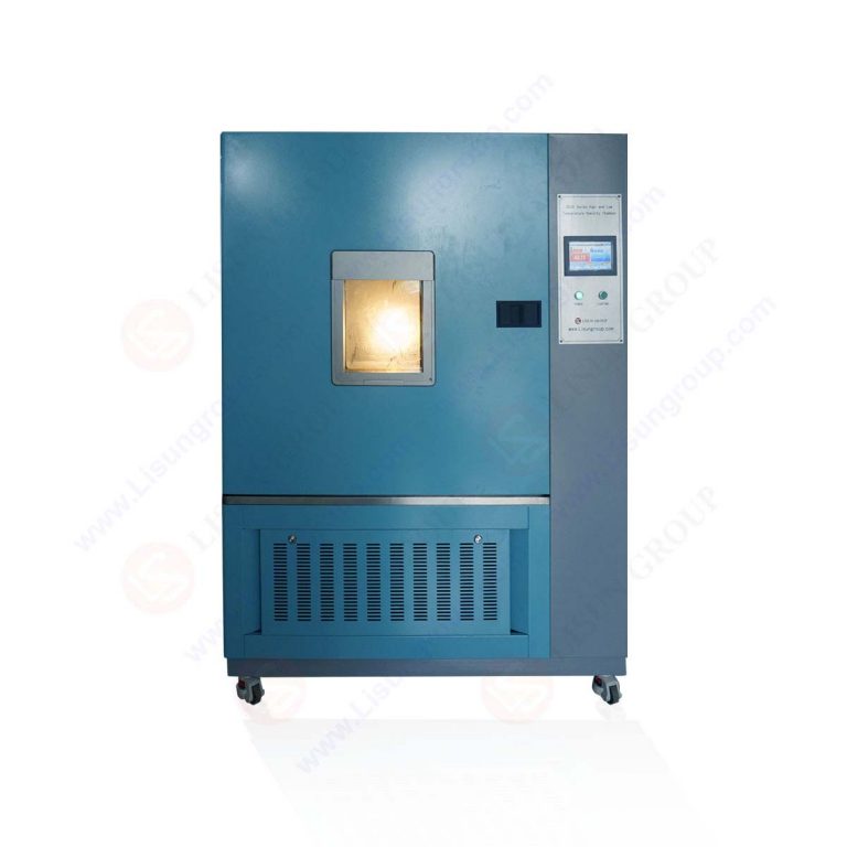
Climatic chambers and thermal chambers serve distinct roles in LED reliability testing, yet their functional boundaries are often misunderstood. A thermal chamber provides precise temperature control—typically ranging from -40°C to +150°C—while a climatic chamber adds humidity regulation, often spanning 20% to 95% relative humidity (RH). For LED lumen maintenance testing under IES LM-80, thermal chambers suffice because the standard mandates dry conditions at specified temperatures (e.g., 55°C, 85°C, and a user-defined third temperature). Conversely, climatic chambers are essential when humidity plays a role in failure mechanisms, such as phosphor degradation or corrosion of LED package interconnects. The Climatic Chamber vs Thermal Chamber: Key Differences Explained framework helps engineers select the appropriate chamber type based on the testing standard and the LED’s intended application environment.
1.2 Relevance to LISUN’s LED Optical Aging Test Instrument
LISUN’s LED Optical Aging Test Instrument integrates seamlessly with both chamber types. The LEDLM-80PL variant, designed for LM-80 compliance, operates optimally in thermal chambers where controlled temperatures drive lumen depreciation without humidity interference. The LEDLM-84PL variant, aligned with LM-84, can accommodate climatic chambers if humidity testing is required for specific failure analysis. Both systems support up to three connected temperature chambers, allowing simultaneous testing at multiple temperatures to accelerate the Arrhenius-based extrapolation. The instruments feature dual testing modes—continuous and cycle-based—enabling engineers to simulate real-world on-off conditions while measuring photometric parameters through an integrating sphere setup. This flexibility underscores the need to understand chamber capabilities before configuring a test protocol.
1.3 Impact of Chamber Selection on Test Outcome Integrity
Selecting the wrong chamber type can introduce systematic errors. For instance, using a climatic chamber when humidity is not controlled—or when condensation occurs on LED surfaces—can corrupt photometric measurements, particularly for correlated color temperature (CCT) and color rendering index (CRI) as defined by CIE 127 and CIE 084. Thermal chambers, on the other hand, may underestimate failure rates in high-humidity environments if the LED’s application (e.g., outdoor or automotive lighting) exposes it to moisture. The Climatic Chamber vs Thermal Chamber: Key Differences Explained analysis reveals that test outcome integrity hinges on matching chamber capabilities to standard-specific requirements, such as those outlined in TM-21 and TM-28 for lumen maintenance projection.
2.1 IES LM-80: Thermal Chamber Specifications for LED Packages
IES LM-80-15 defines the standard for measuring lumen maintenance of solid-state light sources, specifically LED packages, arrays, and modules. It mandates testing at three temperatures: the rated maximum current temperature, a temperature 10°C below that, and either 55°C or 85°C depending on the application. The standard explicitly requires dry conditions, with no humidity control, making thermal chambers the default choice. LISUN’s LEDLM-80PL is engineered to operate in thermal chambers with temperature uniformity within ±2°C, ensuring that the 6000-hour test duration (standard for LM-80) yields reliable data for TM-21 extrapolation to L70 and L50 metrics. The instrument’s software automatically records photometric data every hour, aligned with the Arrhenius Model to predict lumen maintenance at user-defined use temperatures.
2.2 IES LM-84: Flexibility for Climatic Chamber Integration
IES LM-84-22 extends lumen maintenance testing to LED light engines and luminaires, allowing for more complex environmental conditions. While LM-84 primarily requires temperature control, the standard acknowledges humidity as a potential factor for system-level tests where moisture can affect drivers, connectors, or optical elements. Here, the Climatic Chamber vs Thermal Chamber: Key Differences Explained becomes relevant: engineers testing outdoor luminaires (e.g., street lights) may choose climatic chambers to simulate rain, fog, or high-humidity climates. LISUN’s LEDLM-84PL supports this flexibility, featuring a humidity-resistant photometric measurement interface and corrosion-proof integrating sphere components. The instrument’s cycle-based mode can incorporate humidity cycling to mimic diurnal variations, providing comprehensive data for TM-28 extrapolation.
2.3 TM-21 and TM-28: Extrapolation Reliability Depends on Chamber Data
TM-21-19 provides the mathematical framework for extrapolating LM-80 data to project L70 lumen maintenance, while TM-28-22 uses LM-84 data for similar purposes. Both rely on the Arrhenius Model, which assumes that temperature is the primary accelerator of degradation. If thermal chamber data is used with a climatic chamber (or vice versa without adjustment), the activation energy calculation becomes flawed. For example, humidity can lower the activation energy of phosphor thermal quenching, leading to overestimated lifetimes if not accounted for. The LISUN software automatically applies the Arrhenius equation based on the user’s chamber settings, flagging any discrepancy between chamber type and standard requirement. This integration ensures that test reports remain compliant with both IES LM-80 TM-21 and LM-84 TM-28 protocols.
3.1 LEDLM-80PL vs. LEDLM-84PL: Core Differences
| Parameter | LEDLM-80PL | LEDLM-84PL |
|---|---|---|
| Applicable Standard | IES LM-80, TM-21 | IES LM-84, TM-28 |
| Chamber Type Recommendation | Thermal chamber (dry conditions) | Thermal or climatic chamber (humidity optional) |
| Test Duration | 6000 hours (minimum) | 6000 hours (minimum, up to 10,000 hours) |
| Temperature Control Requirement | ±2°C uniformity | ±2°C uniformity (±5% RH for climatic mode) |
| Maximum Connected Chambers | 3 thermal chambers | 3 chambers (thermal or climatic) |
| Photometric Measurement Integration | Integrating sphere (2π or 4π geometry) | Integrating sphere (2π or 4π geometry) |
| Software Capabilities | Arrhenius Model extrapolation to L70/L50 | Arrhenius Model, humidity-adjusted activation energy |
| Dual Testing Modes | Continuous and cycle-based | Continuous, cycle-based, and humidity cycle |
| L70/L50 Metrics | Projected at 6000h, 10000h, based on TM-21 | Projected at 6000h, 10000h, based on TM-28 |
This table clarifies the Climatic Chamber vs Thermal Chamber: Key Differences Explained from an equipment compatibility perspective, enabling engineers to match chamber type with the appropriate LISUN system.
3.2 Arrhenius Model-Based Software: Chamber-Independent Processing
The LISUN software uses the Arrhenius Model to process data from either thermal or climatic chambers. For thermal chamber data, the activation energy is derived solely from temperature-induced degradation. For climatic chamber data, the software incorporates a humidity correction factor, adjusting the Arrhenius equation to account for moisture-mediated failure mechanisms. This feature is critical when testing LEDs for humid environments (e.g., residential or industrial indoor lighting where RH can exceed 80%). The software supports up to 100 LED samples per chamber, with real-time data logging of luminous flux, CCT, CRI, and chromaticity coordinates as per CIE 084 (standard for colorimetry) and CIE 127 (standard for LED measurement). By processing chamber-independent data, the software ensures that the Climatic Chamber vs Thermal Chamber: Key Differences Explained does not compromise extrapolation accuracy.
3.3 Hardware Configurations for Custom Chamber Integration
LISUN’s LED Optical Aging Test Instrument offers customizable hardware interfaces to connect with various chamber models. Key specifications include:
- Temperature range supported: -40°C to +150°C for thermal chambers; -20°C to +85°C for climatic chambers (to avoid condensation on optical sensors)
- Humidity range supported: 20% to 95% RH (non-condensing) for climatic chamber integration
- Integrating sphere diameter: 0.3m, 0.5m, or 1.0m options, depending on LED package size and luminous flux output
- Photometric sensor: Class A spectral response per CIE 127, with a resolution of 0.1 lm for low-power LEDs
- Data acquisition rate: 1 sample per minute (cycling mode) or 1 sample per hour (continuous mode)
These configurations allow engineers to adapt the instrument to existing chamber infrastructure, minimizing capital expenditure while maintaining compliance with IES LM-80 and LM-84 standards.
4.1 Continuous Mode for Steady-State Degradation Analysis
Continuous mode maintains the LED under constant electrical and thermal stress for the entire test duration, typically 6000 hours. This mode is ideal for thermal chamber testing under LM-80, where the Arrhenius Model assumes steady-state acceleration. LISUN’s system records photometric data every hour, capturing the gradual decline in luminous flux without interruption. The Climatic Chamber vs Thermal Chamber: Key Differences Explained is less relevant here because humidity, if present, would introduce unmodeled variability. Therefore, continuous mode is recommended exclusively for thermal chambers, ensuring data consistency for TM-21 extrapolation to L70 and L50 metrics.
4.2 Cycle-Based Mode for Real-World Stress Simulation
Cycle-based mode alternates between on and off states (e.g., 8 hours on, 4 hours off) to simulate the thermal cycling and electrical stress typical in real-world LED applications. This mode is particularly useful for climatic chamber testing under LM-84, where humidity can vary with on-off cycles. The LISUN software includes a programmable cycle profile that can incorporate humidity ramping, allowing engineers to replicate conditions such as outdoor dawn-to-dusk transitions. The Climatic Chamber vs Thermal Chamber: Key Differences Explained becomes critical here: thermal chambers cannot simulate the moisture absorption and desorption that occur during cycling, which can accelerate solder joint fatigue or encapsulant delamination. By using cycle-based mode with a climatic chamber, engineers can identify failure modes missed in steady-state thermal testing.
4.3 Data Management and Extrapolation for Both Modes
LISUN’s software manages data from both modes, applying Arrhenius correction factors for thermal cycling (via the Coffin-Manson model) and humidity cycling (via the Peck model). For cycle-based data from climatic chambers, the software adjusts the activation energy to account for moisture-mediated degradation, as specified in TM-28. The system generates comparative plots of lumen maintenance under continuous vs. cycle-based conditions, enabling engineers to assess the impact of test mode on projected L70 lifetimes. This dual-mode capability reinforces the importance of understanding Climatic Chamber vs Thermal Chamber: Key Differences Explained when designing accelerated aging protocols.
5.1 Integrating Sphere Compatibility for Chamber Setup
LISUN’s integrating sphere is designed for direct integration with both thermal and climatic chambers. For thermal chambers, the optical fiber interface is sealed with a high-temperature gasket to prevent heat loss, maintaining temperature uniformity within ±2°C. For climatic chambers, the fiber interface is moisture-resistant with IP65-rated connectors, preventing condensation from diffracting the photometric signal. The sphere itself is coated with barium sulfate (BaSO4) for diffuse reflectance, compliant with CIE 084 for color measurement. The Climatic Chamber vs Thermal Chamber: Key Differences Explained impacts measurement accuracy: in climatic chambers, humidity can cause spectral shifts in the BaSO4 coating if not controlled, but LISUN’s sphere incorporates a humidity equilibrium vent to maintain coating stability up to 95% RH.
5.2 Spectral Measurement Standards: CIE 127 and CIE 084
CIE 127 specifies methods for total luminous flux measurement using integrating spheres, while CIE 084 defines colorimetric measurement standards. LISUN’s instrument integrates a spectroradiometer with a resolution of 0.1 nm (350-800 nm range), capturing both photometric (luminous flux) and colorimetric (CCT, CRI, chromaticity) data. For thermal chamber testing, the spectroradiometer operates without humidity interference, ensuring compliance with CIE 127 Class A tolerances. For climatic chamber testing, the software applies a humidity correction factor to the spectral data, as humidity can affect the LED’s spectral power distribution (SPD) due to moisture absorption in phosphors. This correction aligns with CIE 084’s guidance for color measurement under varying environmental conditions.
5.3 Impact of Chamber Type on Photometric Accuracy
The Climatic Chamber vs Thermal Chamber: Key Differences Explained directly affects photometric measurement accuracy. In thermal chambers, the only variable is temperature, allowing the integrating sphere to measure light output with high repeatability (less than 0.5% variation over 6000 hours). In climatic chambers, humidity introduces two challenges: first, moisture can cause specular reflections on the LED surface, reducing measured luminous flux; second, humidity can alter the sphere’s reflectance. LISUN’s system mitigates these effects by using a reference detector that monitors sphere wall reflectance during the test, automatically correcting for humidity-induced changes. This ensures that photometric data from climatically tested LEDs remains traceable to standards like CIE 127 and CIE 084.
6.1 Thermal Chamber Testing: Accelerated Aging at High Temperatures
Thermal chambers are ideal for accelerated aging at high temperatures (e.g., 85°C, 105°C, or up to 150°C for short-term tests). LISUN’s LEDLM-80PL supports up to three connected thermal chambers, allowing simultaneous testing at three temperatures (e.g., 55°C, 85°C, 105°C). The Arrhenius Model extrapolates these results to predict L70 lumen maintenance at the use temperature (typically 25°C to 55°C). The Climatic Chamber vs Thermal Chamber: Key Differences Explained emphasizes that thermal chambers offer a simpler, more controlled environment for isolating temperature-driven failures, such as thermal runaway in LED junction temperatures or solder joint fatigue.
6.2 Climatic Chamber Testing: Combined Temperature and Humidity Stress
Climatic chambers enable testing at combined stress levels, such as 85°C/85% RH, which is a standard condition for automotive LED components (e.g., headlights exposed to rain). This condition can reveal failure mechanisms like phosphor hydrolysis (which reduces quantum efficiency) or corrosion of silver-plated lead frames. LISUN’s LEDLM-84PL supports humidity cycles from 20% to 95% RH while maintaining temperature accuracy. The software automatically applies the Peck model (an extension of the Arrhenius model) to account for humidity acceleration, projecting L70 and L50 metrics under real-world damp environments. Engineers must note, however, that data from climatic chambers cannot be directly compared with thermal chamber data unless the software adjusts for the differing acceleration factors.
6.3 Selecting the Appropriate Chamber for Your Test Objective
The decision between thermal and climatic chambers depends on the LED’s application and failure mode priorities. For interior lighting (e.g., office lamps), thermal chambers with continuous mode suffice, as humidity is minimal. For exterior or automotive lighting, climatic chambers with cycle-based mode are necessary. The Climatic Chamber vs Thermal Chamber: Key Differences Explained table below summarizes the decision criteria:
| Test Objective | Recommended Chamber | Standard | LISUN System | Key Metrics |
|---|---|---|---|---|
| LED package lifetime | Thermal | LM-80 / TM-21 | LEDLM-80PL | L70 at 6000h, 10000h |
| Luminaire reliability | Thermal or Climatic | LM-84 / TM-28 | LEDLM-84PL | L70/L50, humidity-adjusted |
| Failure mode analysis (humidity) | Climatic | LM-84 / TM-28 | LEDLM-84PL | Peck model projections |
| High-temperature acceleration | Thermal | LM-80 / TM-21 | LEDLM-80PL | Arrhenius activation energy |
| Real-world cycling (on-off) | Thermal or Climatic | LM-84 | LEDLM-84PL | Coffin-Manson correction |
7.1 Calibration and Verification of Chamber Conditions
Calibration of chamber parameters is mandatory before initiating any LM-80 or LM-84 test. For thermal chambers, the LISUN system includes a temperature verification probe (PT100 RTD) that cross-checks chamber uniformity every 100 hours. For climatic chambers, a humidity verify sensor (capacitive type) is integrated, logging RH values every 10 minutes. The Climatic Chamber vs Thermal Chamber: Key Differences Explained guides here: thermal chamber calibration focuses solely on temperature gradients, while climatic chamber calibration must ensure that humidity does not fall below the dew point (causing condensation on the LED) or exceed the sensor’s saturation limit. LISUN’s software flags any calibration drift exceeding ±2°C or ±5% RH, prompting recalibration.
7.2 Documentation for Regulatory Compliance
Test reports must include chamber type and settings for compliance with IES LM-80, LM-84, TM-21, and TM-28. LISUN’s software automatically generates a report section titled “Chamber Specifications,” which documents temperature and humidity profiles, including data on setpoint stability, ramp rates, and uniformity. The Climatic Chamber vs Thermal Chamber: Key Differences Explained is documented in the report’s “Environmental Conditions” subsection, ensuring that auditors can verify that the test protocol matched the standard’s requirements. For example, reports noting humidity cycling must reference TM-28’s guidance on humidity acceleration factors, while dry thermal chamber reports must cite TM-21’s exclusive temperature-dependence model.
7.3 Case Study: Implementing LISUN Systems for Third-Party Lab Accreditation
A third-party testing lab aiming for IES accreditation can use LISUN’s LED Optical Aging Test Instrument to reduce capital costs by leveraging existing chambers. For example, the lab’s thermal chamber, with ±1°C uniformity at 85°C, can host the LEDLM-80PL for LM-80 testing of LED packages. Simultaneously, a climatic chamber with ±2% RH control at 85°C/85% RH can host the LEDLM-84PL for LM-84 testing of LED luminaires. The Climatic Chamber vs Thermal Chamber: Key Differences Explained ensures that the lab’s test protocols are chamber-appropriate—thermal for packages, climatic for luminaires—minimizing the risk of non-compliant data. LISUN’s dual-system variants allow seamless data integration into a single database, streamlining accreditation processes.
The Climatic Chamber vs Thermal Chamber: Key Differences Explained in this article equips LED testing professionals with the technical knowledge to select, configure, and optimize their environmental chambers for accelerated aging tests. Thermal chambers, suitable for dry-condition standards like IES LM-80 and TM-21, provide a controlled environment for isolating temperature-driven lumen depreciation, with LISUN’s LEDLM-80PL offering precise photometric measurements over 6000-hour tests. Climatic chambers, necessary for humidity-inclusive standards like IES LM-84 and TM-28, enable comprehensive failure analysis for damp-environment LEDs, supported by the LEDLM-84PL’s humidity-adjusted Arrhenius modeling. The integration of LISUN’s dual-mode systems (continuous and cycle-based), Arrhenius software, and customizable hardware (up to three connected chambers, multiple integrating sphere sizes) ensures that test data remains accurate, traceable, and compliant with CIE 084, CIE 127, and IES protocols. For R&D engineers, third-party lab technicians, and compliance specialists, understanding these chamber distinctions is not merely academic—it directly impacts the reliability of L70/L50 projections, the validity of test reports, and the cost-effectiveness of lab operations. LISUN’s solutions provide the flexibility to adopt either chamber type while maintaining the highest measurement standards, making them indispensable tools for modern LED testing.
Q1: Can I use a climatic chamber for IES LM-80 testing if my existing equipment has humidity, but I don’t need it?
A: Yes, you can use a climatic chamber for LM-80 testing, but only if the humidity is actively regulated to remain dry (e.g., below 20% RH at 85°C) to avoid condensation or humidity-induced failure. The LISUN LEDLM-80PL software includes a “dry mode” setting that monitors humidity and flags any spike above 30% RH. However, it is not recommended to use a climatic chamber for LM-80 unless you can maintain a non-condensing environment, as moisture can introduce unmodeled degradation mechanisms, compromising TM-21 extrapolation accuracy. For ideal compliance, a thermal chamber is simpler, cheaper, and more reliable for LM-80.
Q2: How does LISUN’s Arrhenius Model software handle data from both thermal and climatic chambers for L70 projections?
A: The software uses a two-tier processing algorithm. For thermal chamber data, it applies the standard Arrhenius Model with activation energy derived from temperature-dependent flux decay, as per TM-21. For climatic chamber data, it includes a humidity-acceleration factor based on the Peck model, adjusting the activation energy to account for moisture’s role in phosphor and encapsulant degradation. The user selects the chamber type during test setup, and the software automatically chooses the appropriate model. The projected L70 and L50 metrics are clearly labeled as “temperature-only” or “temperature-and-humidity” on the report, ensuring traceability to TM-21 or TM-28 respectively.
Q3: What are the limitations of testing LEDs in a climatic chamber compared to a thermal chamber for LM-84?
A: The primary limitation is the potential for condensation on the integrating sphere’s optical fiber interface, which can scatter light and reduce measurement accuracy. LISUN’s system mitigates this with IP65-rated connectors and a humidity equilibrium vent, but if the chamber’s dew point is reached during rapid temperature cycling (e.g., 85°C to 25°C within 30 minutes), condensation may still occur. Additionally, high humidity (over 95% RH) can degrade the BaSO4 coating of the integrating sphere over long tests (e.g., 10,000 hours). A thermal chamber avoids these issues entirely, but it cannot simulate moisture-driven failures, which are critical for outdoor or automotive LEDs. The trade-off is between comprehensive failure analysis (climatic) and simpler, more reproducible data (thermal).