









Here is a comprehensive technical article on the LISUN DFX series, structured precisely to your specifications.
Abstract
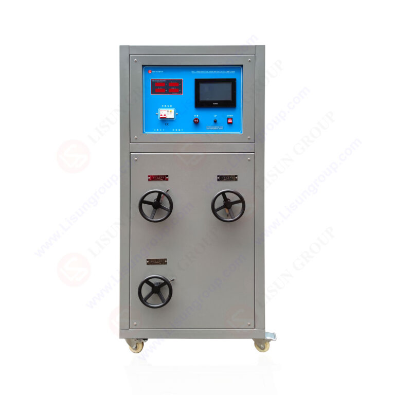
This article provides a technical analysis of the LISUN DFX series Externally Ballasted Fluorescent Lamp Test Load Cabinet, a critical instrument for compliance testing of electrical accessories. Designed for manufacturers and third-party labs, the DFX series simulates the complex electrical characteristics of externally ballasted fluorescent lighting loads, enabling rigorous validation against international standards. This article details the series’ core capabilities, including precise power factor adjustment and multi-channel configurations, which are essential for performing endurance and abnormal condition tests. By replicating the non-linear impedance of real-world installations, the LISUN DFX series Externally Ballasted Fluorescent Lamp Test Load Cabinet ensures that switches, relays, and connectors receive a valid certification assessment under controlled laboratory conditions, reducing field failure risks.
1.1 The Challenge of Simulating Fluorescent Lighting Loads
Fluorescent lamps with external ballasts present a unique electrical load profile characterized by high inrush currents, non-linear current waveforms, and a specific phase relationship between voltage and current. Unlike simple resistive loads, this combination introduces inductive and capacitive reactive components that stress switch contacts and relay mechanisms in a unique manner. Standard resistive load banks cannot replicate the arc quenching demands and thermal stress generated by a ballasted lamp. The LISUN DFX series Externally Ballasted Fluorescent Lamp Test Load Cabinet is engineered to address this complexity, providing a programmable and repeatable load that mimics the exact electrical signature of a 40W to 80W ballasted fluorescent lamp system.
1.2 Role in Electrical Accessory Certification
For compliance with IEC 60669-1 (Switches for household and similar fixed electrical installations) and IEC 61058-1 (Switches for appliances), testing laboratories must prove that a switch can withstand the electrical stress of a controlled number of operations under a defined load. Clause 19.2 of IEC 60669-1 specifically outlines the test circuit for fluorescent lamp loads. The DFX series serves as the dedicated load simulator for these clauses. It replaces the need to use actual lamps and ballasts, which have inconsistent performance and short operational life during endurance testing. This consolidation into a single, ruggedized test cabinet allows for 24/7 automated testing cycles without variability introduced by component aging.
2.1 Circuit Topology and Load Simulation Components
The DFX series utilizes a combination of precision wire-wound resistors, iron-core inductors, and polypropylene capacitors to create the RLC (Resistive-Inductive-Capacitive) network required by standards. The simulation accuracy depends on the stability of these components at elevated temperatures. Each channel within the cabinet is independently configurable, allowing for series or parallel combinations to match the specific power factor (PF) requirements. The DFX-40 model, for instance, provides a standard PF of 0.45 to 0.75, but with specific component selection, it can be tuned to meet the specific crest factor and harmonic content defined in IEC 60669-1 Figure 19.
2.2 Input Power Requirements and Bus Architecture
The system requires a stable mains input, typically single-phase 220VAC or 110VAC, depending on the model. The input current bus is rated to handle the continuous sum of all load channels, with built-in over-temperature protection. For the DFX-80, the maximum continuous current rating is 80 Amperes, which requires a dedicated circuit breaker and appropriate cable cross-sections (typically 16mm² to 25mm²). The internal bus bars are constructed from tinned copper to minimize resistance losses at high current levels, ensuring the voltage at the load point remains within the ±5% tolerance specified in the standard operating conditions.
3.1 Model Differentiation by Capacity
The DFX series includes five primary models: DFX-20, DFX-20-3CH, DFX-40, DFX-60, and DFX-80. The primary differentiators are the maximum continuous current handling capability and the number of independent test channels. The choice of model directly correlates to the number of test stations or the current rating of the Device Under Test (DUT). For example, testing a single 15A switch requires a DFX-20, while testing three separate 15A switches simultaneously recommends the DFX-20-3CH to optimize test time.
3.2 Technical Specification Table
The following table provides a direct comparison of key specifications.
| Model | Max Current (A) | Number of Independent Channels | Typical Application | Input Phase Requirement |
|---|---|---|---|---|
| DFX-20 | 20A | 1 | Single switch or relay test up to 20A | Single Phase |
| DFX-20-3CH | 20A per channel | 3 | Simultaneous test of three 20A switches | Single Phase (High Current) |
| DFX-40 | 40A | 1 | Heavy duty switches or contactors | Single Phase |
| DFX-60 | 60A | 1 | Industrial disconnect switches | Single Phase |
| DFX-80 | 80A | 1 | High-power relay testing | Single Phase |
Note: All models provide power factor adjustment between 0.45 and 0.75. Measurement accuracy for current is ±1% of reading + 3 digits.
4.1 Alignment with IEC and GB Standards
The DFX series is designed to meet the stringent requirements of several international standards.
- IEC 60669-1 (Clause 19.2): This clause defines the test circuit for fluorescent lamp loads. The DFX series must provide a circuit that has a specific impedance at 50/60 Hz. The cabinet achieves this by replicating the parameters of a 40W iron-ballasted lamp, including the characteristic inrush current (typically 10-20 times the steady-state current).
- IEC 60884-1 (Clause 20): For socket-outlets, this clause requires an endurance test with a load representing an external ballast. The DFX series provides the necessary inductive-capacitive load to simulate a floor lamp with external ballast.
- GB 16915.1 (Clause 19): The Chinese national standard for switches, which is technically aligned with IEC 60669-1. The DFX series is factory-calibrated to meet the specific tolerances of GB 16915.1, making it suitable for the China Compulsory Certification (CCC) market.
- IEC 61058-1 (Clause 15): This standard for appliance switches includes test sequences for resistive and inductive loads. The DFX series can be configured to meet the “inductive load” requirements by selecting the appropriate RLC values.
4.2 Performance Verification Table
The following table compares the standard’s minimum requirements with the DFX series performance.
| Parameter | Standard Requirement (IEC 60669-1) | LISUN DFX Series Performance |
|---|---|---|
| Power Factor | 0.45 to 0.75 (depending on test) | 0.45 to 0.75 (Adjustable in 0.01 steps) |
| Load Current Accuracy | ±3% of set value | ±1% of reading + 3 digits |
| Inrush Current Simulation | Required (10x-20x steady state) | Pulse current capability > 200A peak |
| Test Voltage Stability | ±5% at load terminals | ±2% under full load (with proper supply) |
5.1 Compatibility with LISUN Life Test Systems
The primary application of the DFX series is integration with the LISUN CZKS series switch life testers. The DFX cabinet acts as the “load bank” that the CZKS controller connects to. The CZKS unit provides the control logic—timing, cycle counting, and fault detection—while the DFX provides the physical power load. This separation of control and power ensures that the sensitive control electronics are isolated from the high-stress switching transients. A standard workflow involves the CZKS unit activating a relay, which connects the DUT to the DFX load for a specified duration (e.g., 5 seconds ON, 10 seconds OFF).
5.2 Mechanical and Electrical Interfacing
The DFX series uses high-amperage binding posts or bus-bar connections for the power output. These terminals are designed to accept large-gauge test leads (10 AWG or larger). For mechanical integration, the cabinet is designed to fit standard 19-inch racks, allowing it to be placed in a test bay adjacent to the SW-6 bending tester or other mechanical endurance equipment. The remote control interface via DB-25 or RJ-45 connector allows for seamless communication with external PLCs or PC-based test scripts, enabling fully automated 100,000-cycle endurance tests without human intervention.
6.1 Endurance Testing of Rocker Switches
A common use case is the Type Test for a 16A rocker switch. The quality engineer connects the DUT to the DFX-20 channel. The load is configured for a 16A fluorescent lamp load with a power factor of 0.6. The CZKS controller is then programmed for 50,000 cycles at a rate of 15 operations per minute. The DFX cabinet provides the consistent inductive load throughout this duration. Without the DFX, the engineer would need to install 30+ actual lamp and ballast units, which would need replacement multiple times during the test.
6.2 Abnormal Condition Testing (Overload)
The DFX series can also simulate abnormal operation. By adjusting the load capacitance, the engineer can increase the inrush current to represent a fault condition. This is crucial for verifying that a switch can interrupt a circuit under overload without welding the contacts. The DFX series’ ability to sustain a high current surge for several seconds (defined by the test protocol) allows for verification of arc suppression mechanisms within the DUT.
7.1 Periodic Verification of RLC Values
To maintain compliance, the internal resistors and capacitors must be checked annually. The high currents involved cause thermal drift and eventual degradation of the wire-wound resistors. The DFX series features test points on the front panel that allow an engineer to measure the actual current and voltage using a calibrated oscilloscope or power analyzer. The load tolerance is verified by comparing the measured power factor against the set value (e.g., set PF=0.5, verify on the analyzer).
7.2 Thermal Management and Safety Interlocks
The cabinet incorporates forced air cooling with temperature sensors that monitor the internal ambient temperature. If cooling fans fail or if the load exceeds the 80% continuous duty cycle rating, the system engages an interlock that disconnects the power bus. This prevents catastrophic failure of the load components. The safety circuit is a critical feature for unattended overnight testing, which is standard in high-volume certification labs. Regular cleaning of the intake filters is the primary preventative maintenance action required.
The LISUN DFX series Externally Ballasted Fluorescent Lamp Test Load Cabinet represents a critical investment for any organization conducting formal compliance testing of electrical accessories. Its precise simulation of non-linear inductive loads eliminates the variability of real-world ballasts, providing repeatable and defensible test results aligned with IEC 60669-1, IEC 60884-1, and equivalent GB standards. The series’ scalable architecture, ranging from the single-channel DFX-20 to the high-capacity DFX-80, allows laboratories to match capacity to specific testing throughput requirements. When integrated with the LISUN CZKS life tester and SW-6 bending tester, the DFX series forms the core of a robust, automated endurance testing platform. For quality control engineers, the documented load accuracy and adjustable power factor provide the technical control necessary to assure product reliability before market release.
Q1: What is the primary difference between using the LISUN DFX series and a simple resistive load bank for testing switches?
A: The primary difference is the simulation of electrical arc characteristics. A simple resistive load bank only provides a linear voltage-current relationship. Fluorescent lamps with external ballasts create an inductive and capacitive load, causing a phase shift between voltage and current. This phase shift makes the arc harder to extinguish when the switch contacts open. The DFX series specifically replicates this “slow arc” condition by using tuned RLC circuits. Testing with only a resistive load will not stress the switch contacts in the same way, leading to false positives in certification tests. The DFX series ensures compliance with the specific load profiles required by standards like IEC 60669-1 Clause 19.2.
Q2: How do I choose between the DFX-20-3CH and three separate DFX-20 units for my lab?
A: The choice depends on your testing volume and space constraints. The DFX-20-3CH integrates three independent load channels into a single chassis, which saves valuable rack space and requires a single power input connection. However, this comes with a single maximum current bus. If you need to test a single 60A device, you cannot use a DFX-20-3CH. You would need a DFX-60. Conversely, if you are a high-throughput lab testing three 15A switches simultaneously, the DFX-20-3CH is the most space- and cost-effective solution. For maximum flexibility in a large lab, a combination of a DFX-20-3CH and a DFX-40 is often recommended.
Q3: Can the DFX series simulate the load of an LED driver or electronic ballast, or only magnetic ballast loads?
A: The standard DFX series is optimized for magnetic (inductive) ballast loads as required by the traditional international standards. Electronic ballasts operate at high frequencies (typically 20kHz+) and have a very different current profile, often with a high crest factor but a near-unity power factor. The DFX series cannot accurately simulate this high-frequency harmonic content. For testing switches with electronic LED drivers, a different test load configuration is required, often involving a purely capacitive or a highly specific resistive-capacitive network. You should consult the specific test standard (e.g., IEC 60669-2-1) for the correct test circuit for electronic loads. The DFX series remains the definitive solution for legacy magnetic ballast testing.
Q4: What is the typical lifespan of the load components within the DFX cabinet under continuous use?
A: The lifespan is heavily dependent on duty cycle and ambient temperature. Under standard testing conditions (e.g., 15 cycles per minute, 50% duty cycle), the internal resistors and inductors typically have a service life of 5-7 years before the resistance value drifts outside the ±1% tolerance specification. The capacitors, which are polypropylene type, have a longer lifespan (10+ years) as long as they are not subjected to voltage spikes. Regular annual calibration is essential to detect drift. The cooling fans are a wear item and should be checked every 6 months. LISUN recommends stocking a spare fan kit for high-utilization environments to minimize downtime.