Abstract
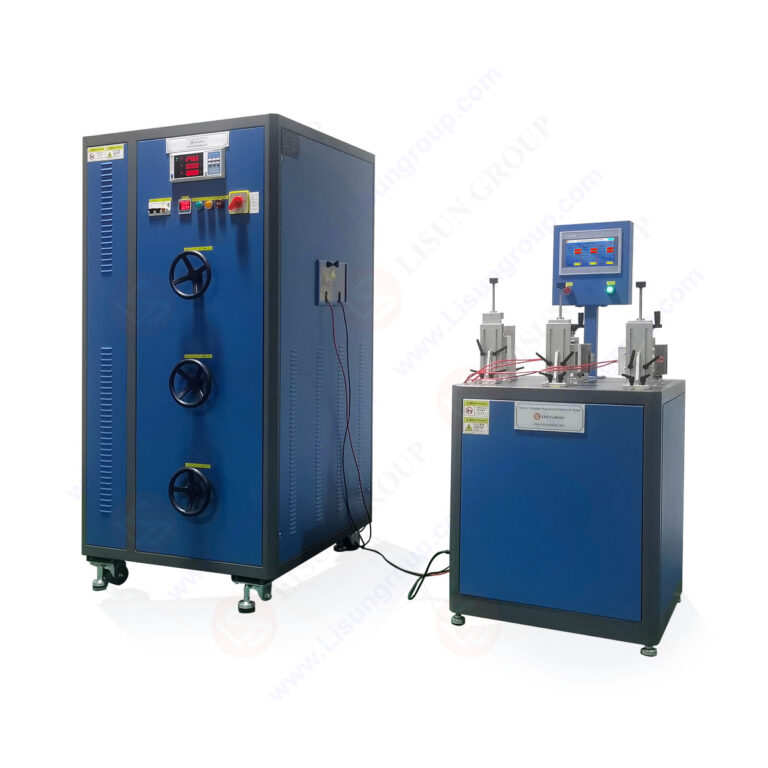
This technical article provides a comprehensive examination of testing methodologies for plugs and socket-outlets under IEC 60884-1 Clause 20, focusing on breaking capacity and durability verification. The core focus addresses how the LISUN CZKS-3 series automated test systems enable compliance with electrical durability testing requirements. Electrical component manufacturers and testing laboratories must ensure that plugs and socket-outlets withstand repeated mechanical and electrical stress without failure. This guide covers test parameter configurations, failure mode analysis, and standard compliance pathways. The LISUN CZKS-3, CZKS-3P, CZKS-3S, and CZKS-3A variants provide tailored solutions for breaking capacity, mechanical endurance, and temperature rise testing. Understanding these methodologies reduces product development risk and accelerates certification processes for household and industrial electrical accessories.
1.1 Scope and Applicability of Breaking Capacity Testing
IEC 60884-1 Clause 20 establishes the normative requirements for breaking capacity testing of plugs and socket-outlets. This clause mandates that electrical accessories must safely interrupt electrical circuits under specified load conditions without causing damage to contacts, insulation, or surrounding components. The breaking capacity test simulates real-world fault scenarios where a plug is withdrawn from a socket-outlet while current is flowing. Testing engineers must configure the test system to deliver repeatable insertion and extraction cycles at controlled rates. The LISUN CZKS-3 series provides precise cylinder-driven actuation that meets the ±5% speed tolerance specified in the standard.
1.2 Electrical Durability Parameters and Measurement Criteria
The durability test protocol under Clause 20 specifies that plugs and socket-outlets must withstand a minimum number of electrical operations—typically 5000 cycles for household applications—without exhibiting contact welding, excessive arcing, or insulation breakdown. Each operation cycle consists of plug insertion, current flow stabilization, and plug extraction under load. Testing parameters include rated voltage (230V or 120V depending on regional standards), rated current (10A, 16A, or 32A), and power factor (0.6 ±0.05 for inductive loads). The LISUN CZKS-3 and its variants incorporate programmable load banks that automatically adjust these parameters throughout the test sequence.
1.3 Failure Mode Classification and Acceptance Criteria
Standard-compliant testing requires systematic documentation of failure modes. Acceptable outcomes include slight contact discoloration and normal mechanical wear. Unacceptable outcomes include:
- Contact welding that prevents plug removal
- Insulation tracking or carbonization beyond permissible limits
- Mechanical deformation affecting insertion force
- Arc propagation causing damage to enclosure materials
The testing engineer must record the cycle count at which any failure mode appears. The LISUN CZKS-3A variant includes integrated high-speed camera triggering and arc detection sensors that capture failure events with millisecond precision, enabling detailed post-test analysis.
2.1 Load Circuit Design and Power Factor Control
Breaking capacity testing requires precise control of the test circuit impedance to achieve the specified power factor. For resistive loads, the power factor approximates unity. For inductive loads representing motor-driven appliances, the power factor must be maintained at 0.6 ±0.05. The test circuit typically includes adjustable resistors and inductors in series with the device under test. The LISUN CZKS-3P variant integrates an automated power factor correction module that maintains target values across the full current range. This eliminates manual adjustments between test cycles and reduces measurement uncertainty.
2.2 Mechanical Actuation Parameters
The mechanical actuation system must replicate human insertion and extraction behavior with consistent velocity profiles. IEC 60884-1 specifies extraction speeds between 0.8 m/s and 1.2 m/s for breaking capacity tests. The actuation mechanism must also maintain perpendicular alignment between plug and socket-outlet faces throughout the operation cycle. Pneumatic or cylinder-driven systems provide the necessary force and repeatability. The LISUN CZKS-3 series uses servo-controlled pneumatic cylinders with closed-loop position feedback, achieving positional accuracy within ±0.1mm and speed stability within ±2% across 100,000+ cycles.
2.3 Environmental Conditioning Requirements
Pre-test conditioning significantly impacts breaking capacity results. Samples must be subjected to:
- Temperature conditioning at 23°C ±2°C for 24 hours prior to testing
- Humidity exposure at 45% to 55% relative humidity for dielectric stability
- Mechanical pre-conditioning of 100 unloaded insertion cycles to normalize contact surfaces
The test environment must maintain temperature within 15°C to 35°C during testing. The LISUN CZKS-3S variant includes an integrated environmental chamber that controls temperature and humidity automatically, ensuring compliance with Clause 20 conditioning requirements without separate equipment.
3.1 Mechanical Endurance Testing Without Electrical Load
Mechanical endurance testing evaluates the structural integrity of socket-outlet mechanisms under repeated insertion and extraction without applied electrical load. This test isolates mechanical wear mechanisms from electrical degradation effects. The standard requires 10000 mechanical cycles for socket-outlets intended for household use. Key measurement parameters include insertion force, extraction force, and dimensional stability of contact receptacles. The LISUN CZKS-3 system includes force transducers that record peak and average insertion forces at programmable intervals, enabling trend analysis of mechanical wear progression.
3.2 Combined Electrical and Mechanical Life Cycle Verification
Combined life cycle testing simultaneously applies electrical load and mechanical actuation to simulate worst-case service conditions. The test sequence alternates between loaded extractions (simulating plug removal while device is active) and unloaded insertions. This protocol stresses both the electrical contact interface and the mechanical retention mechanism. Failure criteria include:
| Parameter | CZKS-3 | CZKS-3P | CZKS-3S | CZKS-3A |
|---|---|---|---|---|
| Max Test Current | 32A | 32A | 32A | 32A |
| Actuation Speed Range | 0.5-1.5 m/s | 0.5-1.5 m/s | 0.5-1.5 m/s | 0.5-1.5 m/s |
| Load Bank Resolution | 0.1A | 0.01A | 0.1A | 0.01A |
| Data Logging Channels | 8 | 16 | 8 | 32 |
| Environmental Control | No | No | Yes | Yes |
The table above demonstrates how each CZKS-3 variant addresses specific testing requirements. The CZKS-3A variant provides the highest channel count for comprehensive multi-sample testing, while the CZKS-3S includes environmental control for conditioned testing.
3.3 Automotive Component Durability Considerations
Automotive plugs and socket-outlets, conforming to standards such as ISO 8092 or SAE J1742, require modified durability parameters. The test environment must accommodate higher vibration levels and temperature extremes from -40°C to +125°C. Contact retention force requirements are typically 30% higher than household applications due to vehicle movement-induced stress. The LISUN CZKS-3P variant supports programmable vibration profiles and temperature cycling sequences, making it suitable for automotive connector manufacturers seeking dual compliance with IEC 60884-1 and automotive-specific standards.
4.1 System Architecture and Signal Processing
Modern plug and socket-outlet test systems employ programmable logic controllers (PLCs) for precise test execution sequencing. The PLC manages pneumatic valve timing, load bank switching, and data acquisition synchronization. The control architecture includes digital inputs for limit switches and analog inputs for current and voltage transducers. The LISUN CZKS-3 series utilizes a modular PLC system with expandable I/O modules, enabling configuration for up to 32 simultaneous test channels. Real-time signal processing at 10kHz sampling rates captures transient events including arcing duration and contact bounce.
4.2 User-Programmable Test Sequences
The testing engineer must configure test sequences that comply with specific standard clauses while accommodating product-specific requirements. Programmable parameters include:
- Number of pre-conditioning cycles
- Load application timing relative to actuation position
- Dwell time between insertion and extraction
- Data logging intervals for contact resistance measurement
- Emergency stop criteria based on current threshold exceedance
The LISUN CZKS-3 series control software provides a graphical sequence editor that allows drag-and-drop configuration without specialized programming skills. Pre-loaded templates for IEC 60884-1 Clause 20, IEC 60669-1 for switches, and IEC 61058-1 for appliance switches reduce setup time.
4.3 Data Acquisition and Reporting Automation
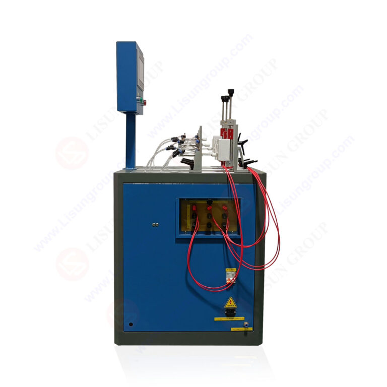
Automated data acquisition eliminates manual transcription errors and provides traceable test records. The system records time-stamped measurements of voltage, current, power factor, contact resistance, and actuation force for each cycle. Statistical analysis functions compute mean, standard deviation, and maximum values across cycle blocks. The reporting module generates standard-compliant test reports that include:
- Test configuration parameters
- Raw measurement data in tabular format
- Graphical trend plots for contact resistance and insertion force
- Failure event annotations with timestamps and photographs
The CZKS-3A variant includes a 24-hour unattended operation capability with automatic replenishment of consumable samples via a magazine feed system.
5.1 Switch Durability Testing Under IEC 60669-1
IEC 60669-1 covers switches for household and similar fixed electrical installations. Clause 19 of this standard specifies mechanical endurance of 100000 operations for switches rated above 10A. The test protocol differs from plug testing in that the switch mechanism remains fixed while the actuating member cycles. Contact gap measurement before and after testing verifies that arc erosion has not reduced dielectric clearance below minimum values. The LISUN CZKS-3P variant supports interchangeable actuation heads that accommodate rocker switches, push-button switches, and rotary switches using the same base system.
5.2 Appliance Switch Testing Under IEC 61058-1
IEC 61058-1 applies to switches integrated into electrical appliances. These switches experience lower mechanical loads but higher electrical stress due to inrush currents from appliance motors. Clause 17 requires electrical endurance testing at 1.1 times rated current with power factor of 0.75. Testing engineers must configure the load bank to simulate specific appliance loads, including capacitive and inductive components. The LISUN CZKS-3 series programmable load bank includes pre-set profiles for common appliance types including vacuum cleaners, power tools, and kitchen appliances.
5.3 Multi-Standard Compliance Strategy
Manufacturers exporting products globally must demonstrate compliance with multiple standards using a unified testing approach. The test system must accommodate:
- Voltage selection: 100-250V for global market coverage
- Frequency selection: 50Hz and 60Hz for international compatibility
- Socket-outlet standards: European Schuko, British BS 1363, American NEMA configurations
The LISUN CZKS-3A variant includes interchangeable socket-outlet adapters and voltage/frequency switching that enables sequential testing across standards without system reconfiguration. This reduces certification cycle time by up to 40% compared to single-standard test systems.
6.1 Four-Wire Kelvin Measurement Implementation
Contact resistance measurement during durability testing requires four-wire Kelvin configuration to eliminate lead and contact resistance errors. The measurement current must be DC to avoid inductive effects, typically 100mA to 1A depending on the expected resistance range. Acceptable contact resistance values for new plugs and socket-outlets range from 5 to 20 milliohms at rated current. The CZKS-3 series integrates dedicated four-wire measurement channels with 0.1 milliohm resolution and automatic temperature compensation based on the reference junction.
6.2 Degradation Trend Analysis and Predictive Maintenance
Contact resistance degradation follows a characteristic curve: initial stabilization, steady-state operation, and rapid deterioration before failure. Monitoring the rate of resistance increase enables predictive maintenance scheduling before catastrophic failure occurs. The testing engineer sets resistance threshold alarms that trigger test interruption when values exceed 200% of initial measurements. The LISUN CZKS-3P control software includes trend analysis algorithms that calculate the resistance change rate and estimate remaining useful life based on historical data from similar product types.
6.3 Arc Energy Quantification and Contact Material Optimization
Arc energy during plug extraction directly correlates with contact material erosion rate. Integration of voltage and current waveforms during the arc period enables calculation of instantaneous power and cumulative arc energy. Silver-alloy contacts typical in household socket-outlets exhibit predictable erosion rates of 0.1-0.5 micrograms per arc event at 16A resistive load. The CZKS-3A variant includes high-bandwidth current and voltage sensors (1MHz sampling) that capture arc initiation and extinction characteristics for material optimization studies.
7.1 Steady-State Temperature Measurement Protocols
Temperature rise testing under load verifies that plug and socket-outlet contacts do not exceed the 45°C rise limit specified in IEC 60884-1 Clause 23. Thermocouples are attached to contact surfaces, wire termination points, and enclosure surfaces. The test current is applied for sufficient time to achieve thermal equilibrium, typically 4 hours for household socket-outlets. The LISUN CZKS-3S variant includes 16 thermocouple input channels with cold-junction compensation and automatic data logging at 1-minute intervals during the stabilization period.
7.2 Current Derating and Thermal Simulation Correlation
Ambient temperature affects current-carrying capacity through the relationship defined by the Arrhenius equation for contact material oxidation kinetics. Testing engineers must correlate thermal simulation results with physical measurements to validate product designs. Key parameters for thermal analysis include:
- Contact interface thermal resistance (0.5-2.0 K/W depending on material and force)
- Conductor cross-sectional area effect on I²R losses
- Enclosure ventilation impact on convective heat transfer
The CZKS-3 series programmable current source supports derating profiles that simulate elevated ambient temperatures up to 85°C for automotive applications.
7.3 Thermal Imaging Integration for Hotspot Detection
Infrared thermal imaging during testing reveals localized heating at contact interfaces that may not be captured by discrete thermocouple placement. Temperature gradients across contact surfaces indicate uneven current distribution or partial contact separation. The CZKS-3A variant includes synchronization output for external thermal cameras, enabling frame-by-frame correlation with electrical measurement data. This integrated approach identifies failure precursors that appear 100-500 cycles before electrical failure occurs.
The IEC 60884-1 Clause 20 testing framework establishes rigorous requirements for plug and socket-outlet breaking capacity and electrical durability verification. Electrical component manufacturers must implement automated test systems that deliver precise mechanical actuation, controlled electrical loading, and comprehensive data acquisition to achieve compliance efficiently. The LISUN CZKS-3 series, including its CZKS-3P, CZKS-3S, and CZKS-3A variants, provides an integrated solution that addresses breaking capacity testing, mechanical endurance, temperature rise measurement, and multi-standard compliance verification. Testing laboratories benefit from PLC-based automation that reduces operator dependency and increases measurement reproducibility. The inclusion of contact resistance monitoring, arc energy quantification, and thermal analysis capabilities enables predictive failure analysis that reduces product development risk. Manufacturers serving household, industrial, and automotive markets can consolidate their testing infrastructure around a single platform that adapts to evolving standard requirements. By implementing the methodologies described in this guide, testing engineers can reduce certification cycle times while maintaining the measurement accuracy demanded by international safety standards.
Q1: What is the difference between breaking capacity testing and mechanical endurance testing for plug and socket-outlets under IEC 60884-1?
A: Breaking capacity testing evaluates the ability of a plug and socket-outlet combination to safely interrupt an electrical circuit while current is flowing. This test simulates the scenario where a user pulls a plug from a socket while an appliance is operating. The test applies rated voltage and current with a specified power factor, typically 0.6 for inductive loads. Mechanical endurance testing, by contrast, evaluates structural integrity through repeated insertion and extraction cycles without electrical load. Breaking capacity testing requires 5000 cycles minimum, while mechanical endurance testing without load requires 10000 cycles. The LISUN CZKS-3 series automates both protocols by switching between loaded and unloaded test sequences, reducing equipment duplication.
Q2: How does the LISUN CZKS-3 series ensure accuracy in power factor control during breaking capacity tests?
A: The LISUN CZKS-3 series, particularly the CZKS-3P variant, employs an automated power factor correction module that maintains the target power factor within ±0.02 of the specified value throughout the test duration. The system uses a programmable inductor bank with 64 discrete inductance values combined with a fine-adjustment variable inductor. Real-time feedback from voltage and current phase angle measurement at 10kHz sampling rate drives PID control algorithms that adjust the inductance within 50ms. This eliminates the manual adjustment required by conventional test systems and ensures compliance with the IEC 60884-1 requirement of power factor 0.6 ±0.05. The control system also compensates for changes in contact resistance and load temperature that would otherwise shift the circuit impedance.
Q3: Can the CZKS-3 series test automotive-grade connectors that require different environmental conditions than household socket-outlets?
A: Yes, the CZKS-3S variant includes an integrated environmental chamber that controls temperature from -40°C to +125°C and humidity from 10% to 95% relative humidity, covering the typical range for automotive connector testing per ISO 8092 and USCAR-2 standards. The actuation system uses high-temperature pneumatic seals and lubricants rated for continuous operation at 125°C. Additionally, the vibration table option provides sinusoidal and random vibration profiles from 5Hz to 2000Hz at amplitudes up to 5g. Testing engineers can configure sequential test profiles that apply temperature cycling, vibration, and electrical loading in any combination. The CZKS-3A variant supports 32 channels for simultaneous testing of multiple automotive connector types, making it suitable for high-volume production validation.
Q4: What data analysis capabilities are available in the CZKS-3 series for identifying failure precursors during durability testing?
A: The CZKS-3 series control software includes statistical process control (SPC) functions that analyze contact resistance trends, insertion force profiles, and arc duration distributions. The system calculates moving averages and standard deviations over selectable cycle windows, typically 50 to 500 cycles. When the contact resistance exceeds three standard deviations above the moving average, the system flags the event and automatically increases data logging frequency. The predictive failure algorithm correlates resistance increase rate with historical data to estimate remaining useful life. The CZKS-3A variant adds neural network-based pattern recognition that identifies arc signature changes corresponding to specific failure modes such as contact material transfer or spring tension loss. Reports include Weibull distribution analysis for reliability engineering applications.
Q5: How does the CZKS-3 series accommodate testing of non-standard socket-outlet geometries encountered in global markets?
A: The LISUN CZKS-3 series utilizes a modular fixture plate system that accepts interchangeable socket-outlet adapters for all major international standards including European Schuko (CEE 7/4), British BS 1363, American NEMA 5-15, Australian AS/NZS 3112, and Chinese GB 2099.1. The adapters include integrated force sensors and temperature measurement points at standard locations. The actuation head adjusts height and angle automatically using servo-controlled positioning to accommodate plug geometries from 10mm to 60mm diameter. The control software includes pre-loaded dimensional profiles for each standard, enabling automatic configuration changes. The CZKS-3P variant supports motor-driven X-Y positioning of the fixture plate for testing of multi-socket strips with up to 14 outlet positions without manual repositioning.