Abstract
This technical article examines the comprehensive testing methodologies for switch and socket durability compliance under GB/T 15092.1-2020, with a focus on LISUN CZKS-3 series automated test solutions. GB/T 15092.1-2020 switch testing requires precise mechanical actuation, electrical load control, and failure detection capabilities that modern automated systems must deliver. The LISUN CZKS-3 series, including variants CZKS-3P, CZKS-3S, and CZKS-3A, provides integrated solutions for breaking capacity verification, mechanical endurance assessment, and electrical fatigue life testing. This article analyzes the technical requirements of GB/T 15092.1-2020, the corresponding test parameters, and the engineering principles behind compliant test system design. Electrical component manufacturers and safety testing laboratories will find detailed guidance on implementing cost-effective, standards-compliant testing protocols using the CZKS-3 series platforms for household and automotive electronics applications.
1.1 Scope and Applicability of the Standard
GB/T 15092.1-2020 represents the Chinese national standard governing safety and performance requirements for switches used in household and similar fixed electrical installations. This standard aligns closely with IEC 61058-1, establishing test criteria for mechanical durability, electrical endurance, and thermal stability. The standard applies to manually operated switches rated up to 440 V and 63 A for general use, as well as switches integrated into appliances and automotive applications. Compliance with GB/T 15092.1-2020 switch testing ensures that products can withstand the rigors of prolonged service without compromising safety.
1.2 Key Test Parameters Defined in the Standard
The standard specifies stringent test conditions for evaluating switch performance under normal and abnormal operating scenarios. Mechanical endurance testing requires switches to complete 10,000 to 100,000 cycles depending on the switch category, with each cycle representing a full open-close operation. Electrical endurance tests subject switches to rated current at rated voltage for a specified number of operations, typically 1,000 to 10,000 cycles. The standard also mandates breaking capacity tests where switches must interrupt fault currents up to 1.5 times the rated current. Temperature rise measurements during these tests must not exceed specified limits, typically 45 K above ambient for current-carrying parts. The LISUN CZKS-3 series is engineered to accommodate all these test parameters with precision control and automated data logging.
2.1 System Design and Mechanical Actuation
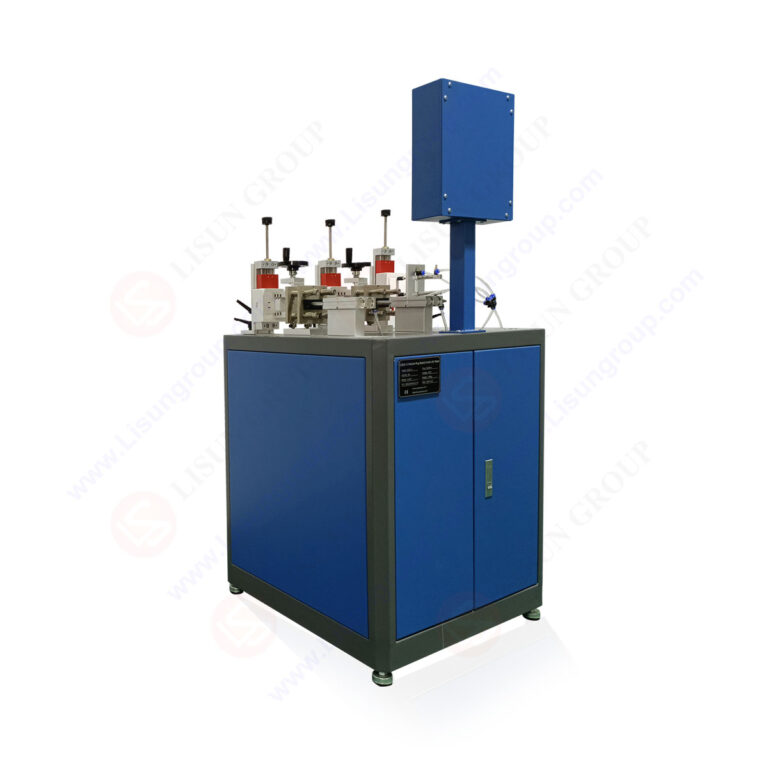
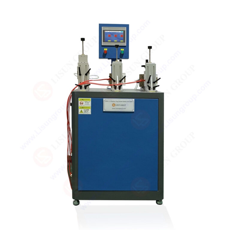
The LISUN CZKS-3 series incorporates a modular architecture based on PLC-controlled cylinder-driven actuation mechanisms. Each test station features independent pneumatic cylinders with adjustable stroke length, actuation force, and dwell time parameters. The CZKS-3 base model supports single-station testing, while the CZKS-3P variant provides parallel testing capability for up to three switches simultaneously. Force sensors integrated into each actuation head provide real-time feedback, enabling the system to detect mechanical failures such as contact welding or actuator jamming. The actuation rate ranges from 5 to 30 cycles per minute, configurable through the system’s touchscreen interface.
2.2 Electrical Load Control and Monitoring
A critical feature of the LISUN CZKS-3A variant is its advanced electrical load control system. The unit incorporates programmable AC and DC power supplies capable of delivering test voltages up to 440 V AC and currents up to 63 A. Real-time current and voltage monitoring at 10 kHz sampling rates allows detection of contact bounce, arcing duration, and transition resistance changes. The system automatically logs failure events when parameters exceed user-defined thresholds. For the CZKS-3S variant, enhanced safety isolation is provided through galvanically isolated measurement channels, ensuring operator protection during high-energy tests. The system supports both resistive and inductive load configurations to simulate real-world electrical conditions.
2.3 Technical Comparison of CZKS-3 Series Variants
The following table summarizes the key technical specifications across the CZKS-3 series product line:
| Parameter | CZKS-3 | CZKS-3P | CZKS-3S | CZKS-3A |
|---|---|---|---|---|
| Test Stations | 1 | 3 | 1 | 1 |
| Max Test Voltage | 250 V AC | 250 V AC | 440 V AC | 440 V AC |
| Max Test Current | 32 A | 32 A | 63 A | 63 A |
| Sampling Rate | 1 kHz | 1 kHz | 10 kHz | 10 kHz |
| Fault Detection Types | 3 | 3 | 5 | 6 |
| Load Type Support | Resistive | Resistive | Resistive/Inductive | Resistive/Inductive/Capacitive |
| Isolation Rating | Basic | Basic | Enhanced | Enhanced |
| Data Export | USB | USB | Ethernet/USB | Ethernet/USB |
3.1 Test Protocol According to GB/T 15092.1-2020, Clause 17
Breaking capacity testing under GB/T 15092.1-2020, clause 17, evaluates a switch’s ability to safely interrupt fault currents without causing arcing damage or contact welding. The test procedure requires applying 1.5 times the rated current at rated voltage for 50 operations, with each operation consisting of a make-break sequence. The LISUN CZKS-3A variant excels in this application, as its programmable load bank can automatically sequence through the required load profiles. The system records arc duration, peak current, and contact voltage drop for each operation, providing comprehensive data for compliance documentation.
3.2 Application in Socket Breaking Capacity Verification
Socket breaking capacity testing extends the same principles to receptacle-type devices, where the test involves inserting and withdrawing a test plug under load. This application requires precise alignment between the plug insertion mechanism and the socket under test. The CZKS-3S variant includes a dedicated socket fixture with adjustable clamping force and alignment guides, ensuring consistent insertion depth across repeated cycles. During breaking capacity tests, the system monitors for evidence of flashover, tracking, or insulation degradation. Test results automatically compare against the acceptance criteria defined in GB/T 15092.1-2020, clause 17.3, which requires that no continuous arcing occurs and that contacts show minimal erosion after testing.
4.1 Mechanical Endurance Assessment Under Clause 18
Mechanical endurance testing evaluates switch operation under no-load conditions to verify that the mechanical actuation mechanism can withstand extended use. The standard specifies minimum cycle counts based on switch classification: 100,000 cycles for switches rated for frequent operation, 50,000 for standard household switches, and 10,000 for infrequently operated devices. The LISUN CZKS-3P variant efficiently handles this requirement through its parallel test architecture, allowing three switches to undergo simultaneous endurance testing. Each test station independently monitors actuation force profiles, detecting any increase that indicates bearing wear or spring fatigue. The system automatically halts testing if force exceeds user-defined thresholds, preventing damage to both the test specimen and the test equipment.
4.2 Electrical Endurance Testing Under Combined Load Conditions
Electrical endurance testing combines mechanical actuation with electrical load application, simulating real-world usage patterns. The standard requires switches to complete a specified number of operations at rated voltage and current, typically with a power factor of 0.6 for AC circuits. The LISUN CZKS-3A variant provides programmable load profiles that can switch between resistive, inductive, and mixed loads during a single test sequence. For automotive switch applications, the system supports 12 V and 24 V DC testing with currents up to 30 A, complying with the relevant clauses of GB/T 15092.1-2020. Contact resistance measurements taken at regular intervals throughout the test reveal degradation trends, with a typical pass criterion being less than 1.5 times the initial contact resistance after 10,000 operations.
5.1 Testing Wall Switches and Dimmers
Household wall switches present unique testing challenges due to their varied actuation mechanisms, including toggle, rocker, and push-button configurations. The LISUN CZKS-3 series accommodates these form factors through interchangeable actuation heads that match the switch geometry. For dimmer switches, the system can programmatically adjust the test voltage and current levels to simulate dimming cycles at 10%, 50%, and 100% output levels. The CZKS-3S variant includes a harmonic analysis module that measures voltage and current waveforms during dimmer operation, identifying any distortion that could indicate semiconductor device stress. These measurements are critical for compliance with the appropriate clauses of GB/T 15092.1-2020.
5.2 Testing Appliance Switches and Selectors
Appliance switches, including rotary selectors and multi-pole switches, require multi-axis actuation that standard linear test systems cannot provide. The CZKS-3P variant can be configured with a rotary actuation module that applies controlled torque to switch shafts while simultaneously measuring angular position and actuation force. This capability supports testing of appliance switches used in washing machines, dishwashers, and kitchen appliances where multi-position selection is required. The system logs the torque profile for each position transition, detecting any increase that indicates mechanical binding or contact wear. Data from these tests directly supports compliance documentation for the unique switch categories covered under GB/T 15092.1-2020.
6.1 Special Requirements for Automotive Components
Automotive switches must withstand more severe environmental and electrical conditions than household switches, including wide temperature ranges (-40°C to 85°C), vibration, and exposure to moisture and contaminants. While GB/T 15092.1-2020 provides the foundational framework, automotive applications often reference additional standards such as ISO 7588 for switching devices in road vehicles. The LISUN CZKS-3A variant supports extended temperature testing through its optional thermal chamber integration, allowing switches to be tested at specified temperature extremes while under electrical load. This capability is essential for verifying switch performance in engine compartments, door modules, and dashboard controls.
6.2 Testing Power Window and Seat Switches
Power window switches and power seat adjustment switches require high-current DC testing with motor loads that generate inductive kickback during switch-off transitions. The CZKS-3S variant includes an inductive load simulator specifically designed for automotive applications, capable of creating load profiles equivalent to DC motors up to 200 W. The system’s high-speed sampling at 10 kHz captures the voltage transient during switch opening, allowing engineers to verify that arc suppression measures are adequate. Contact adhesion failures, where contacts weld due to sustained arcing, are automatically detected through resistance monitoring during the switch-off state. This detection capability is crucial for compliance with the failure mode analysis requirements in GB/T 15092.1-2020.
7.1 Automated Data Acquisition and Analysis
The LISUN CZKS-3 series integrates comprehensive data acquisition systems that record all test parameters at configurable intervals. For long-duration endurance tests spanning days or weeks, the system stores historical data in compressed format, retaining fault events with millisecond resolution. The software platform provides real-time visualization of key parameters, including cycle count, actuation force trend, and contact resistance progression. Statistical analysis tools calculate mean time between failures (MTBF), Weibull distribution parameters, and cumulative probability curves. These analytical outputs are directly usable in compliance documentation for GB/T 15092.1-2020 switch testing submissions.
7.2 Report Generation for Audits and Certifications
The test management software generates comprehensive reports that include all required data from the standard’s test clauses, including test conditions, measured values, and pass/fail determinations. Reports can be customized to include company logos, device photographs, and technician signatures. The system supports export in PDF, Excel, and XML formats for integration with laboratory information management systems (LIMS). For certification bodies requiring electronic submission, the XML export includes structured data fields corresponding to specific clauses of GB/T 15092.1-2020. This automated reporting capability reduces documentation errors and accelerates the certification process for new switch products.
The GB/T 15092.1-2020 switch testing standard establishes rigorous requirements for verifying the safety and durability of electrical switches used in household and automotive applications. Successful compliance requires test equipment that can deliver precise mechanical actuation, controlled electrical loading, and comprehensive failure detection across thousands or hundreds of thousands of operating cycles. The LISUN CZKS-3 series, including the CZKS-3, CZKS-3P, CZKS-3S, and CZKS-3A variants, provides a scalable platform that addresses the full spectrum of testing requirements defined in the standard. From breaking capacity verification to long-term endurance assessment, these systems integrate PLC-controlled actuation, programmable load banks, and high-speed data acquisition to deliver reliable, repeatable results. Electrical component manufacturers and testing laboratories benefit from the system’s modular design, which allows configuration for specific test applications while maintaining compliance with international standards including IEC 61058-1, IEC 60884-1, and GB/T 2099.1. By automating the testing process and providing comprehensive data management capabilities, the CZKS-3 series reduces testing time, improves accuracy, and simplifies the creation of compliance documentation. For organizations committed to producing safe, reliable switch products, investing in standards-compliant testing infrastructure is not merely a regulatory requirement but a fundamental aspect of quality assurance and brand protection.
Q1: What is the difference between GB/T 15092.1-2020 and IEC 61058-1 for switch testing?
A: GB/T 15092.1-2020 is the Chinese national adoption of IEC 61058-1 with some national deviations specific to the Chinese market. While the core test requirements—including mechanical endurance, electrical endurance, and breaking capacity—are essentially identical, GB/T 15092.1-2020 includes additional clauses addressing local safety practices and product categories common in Chinese electrical installations. For manufacturers exporting switches to China, compliance with GB/T 15092.1-2020 switch testing is mandatory, whereas IEC 61058-1 compliance may be accepted in other markets. The LISUN CZKS-3 series supports both standards through configurable test parameters, allowing laboratories to switch between the two regulatory frameworks without hardware changes.
Q2: How does the CZKS-3A variant handle inductive load testing for motor-driven switches?
A: The CZKS-3A variant incorporates a programmable inductive load simulator that replicates the electrical characteristics of motors, solenoids, and transformers. The simulator uses variable inductance coils with adjustable air gaps to achieve power factors ranging from 0.3 to 0.8 at 50/60 Hz. For DC applications, the system includes a flyback diode simulator and customizable inductive kickback profiles. The load bank is controlled via the PLC system, allowing automatic switching between resistive, inductive, and mixed modes during a single test sequence. Real-time current and voltage monitoring at 10 kHz captures transient events during switch-off, including arc duration and peak voltage, which are critical for evaluating contact erosion rates and determining switch lifetime under motor load conditions. This capability is essential for compliance with the electrical endurance clauses of GB/T 15092.1-2020.
Q3: What maintenance is required to keep the LISUN CZKS-3 series accurate for long-term testing?
A: Routine maintenance for the CZKS-3 series includes three key areas: pneumatic system servicing, electrical calibration, and mechanical alignment verification. Pneumatic cylinders and solenoid valves should be inspected quarterly for seal wear and lubricated according to the manufacturer’s specifications. Electrical calibration, including current sensors, voltage transducers, and power analyzers, should be performed annually using traceable reference standards. Mechanical alignment verification involves checking that actuation rods and fixtures maintain perpendicular alignment to test specimens within 0.5 mm tolerance. The system’s self-diagnostic software provides automated calibration checks and drift detection, generating alerts when sensor readings deviate from factory baselines. These procedures ensure that test results remain accurate and repeatable over the system’s operational lifetime.
Q4: Can the CZKS-3P variant test three different switch models simultaneously?
A: Yes, the CZKS-3P variant supports independent test programming for each of its three stations, allowing simultaneous testing of different switch models with different test parameters. Each station has its own PLC-controlled actuation cylinder, load circuit, and measurement channel, enabling completely independent test sequences. The operator can configure each station’s cycle count, actuation force, dwell time, and electrical load parameters through the system’s touchscreen interface. This parallel testing capability significantly increases laboratory throughput without requiring multiple test systems. However, for breaking capacity tests requiring high fault currents, it is recommended to operate only one station at a time to ensure available power supply capacity. The system automatically manages this limitation through its load scheduling feature.
Q5: What failure detection methods does the CZKS-3 series use for contact welding during endurance tests?
A: The CZKS-3 series employs a multi-layered failure detection strategy for identifying contact welding and adhesion. The primary detection method involves measuring the voltage drop across closed contacts during the load-on phase; if the voltage drop drops below a threshold indicating welded contacts remain closed, the system triggers a failure alarm. Secondary detection uses force monitoring during the actuation stroke—a sudden increase in required actuation force while the electrical circuit remains closed indicates partial welding. The system also monitors the contact open time relative to the actuation command, where delayed opening beyond specified tolerances signals adhesion. These detection methods operate at the system’s sampling rate of 1 kHz to 10 kHz, ensuring that even brief transient welding events are captured. Upon detection, the system halts the test and records the event with a timestamp, cycle count, and pre- and post-failure measurement data for engineering analysis.