


Metrological Verification of Plug and Socket Safety: An Analysis of the NF C 61-314 C5 Gauge and Its Implementation
Abstract
The integrity of electrical connections within plugs and sockets is a foundational element of electrical safety, directly impacting the prevention of electric shock, fire hazards, and equipment failure. International and national standards, such as the French NF C 61-314, prescribe rigorous dimensional and mechanical requirements for these components. Compliance verification necessitates the use of specialized, calibrated test gauges. This technical article examines the specification, application, and critical importance of the NF C 61-314 C5 gauge, a device designed to assess the dimensional compliance of socket-outlet contacts. Furthermore, it details the implementation of this standard through advanced testing equipment, specifically the LISUN Gauges for Plugs and Sockets, which provide a comprehensive, reliable, and traceable solution for manufacturers and certification bodies.
The Regulatory Framework of NF C 61-314
The NF C 61-314 standard, titled “Plugs and socket-outlets for household and similar purposes,” is the French transposition of the harmonized European standard EN 50075 and is aligned with the international IEC 60884-1 specification. Its primary objective is to define the safety requirements for plugs and fixed or portable socket-outlets with a rated voltage not exceeding 250 V and a rated current not exceeding 16 A, intended for household and similar purposes. The standard encompasses a multitude of safety aspects, including but not limited to: protection against electric shock, temperature rise limits, durability, resistance to mechanical stress, and crucially, the dimensional accuracy of live parts.
Dimensional non-conformity presents a significant risk. Oversized socket contacts may fail to maintain adequate contact pressure on a plug pin, leading to arcing, overheating, and potential ignition. Conversely, undersized contacts can impose excessive insertion and withdrawal forces, damaging the plug and socket, and posing a physical strain on the user. The standard, therefore, defines precise maximum and minimum dimensions for the socket contact tubes. The C5 gauge, as a “go/no-go” tool, is the metrological instrument prescribed to validate that these critical dimensions remain within the permissible tolerance zones, ensuring both safety and functional interoperability.
Anatomy and Functional Principle of the C5 Gauge
The NF C 61-314 C5 gauge is a precision mechanical instrument fabricated from a durable, dimensionally stable material, typically hardened steel or brass, to resist wear and maintain calibration integrity over thousands of test cycles. Its design is a physical embodiment of the dimensional limits specified in the standard for the socket-outlet’s phase and neutral contacts.
The gauge consists of two primary elements: a “GO” member and a “NO-GO” member, often integrated into a single, handheld tool. The “GO” member is a cylindrical pin whose diameter corresponds to the maximum allowable size of a plug pin plus a defined tolerance. This member must be insertable into the socket contact with a specified force, verifying that the contact is sufficiently open to accept a standard plug without excessive force. The “NO-GO” member, typically a tapered or stepped pin, has a diameter that represents the minimum acceptable size for the socket contact opening. This member must not be insertable into the contact beyond a specified depth or under a defined force, confirming that the contact has not become overly widened, which would compromise its gripping force on a plug pin.
The application of the gauge is a binary test. A socket outlet passes only if the “GO” member can be fully inserted and the “NO-GO” member is rejected. This simple yet effective principle provides an unambiguous assessment of the contact’s dimensional conformity.
Integration into Automated Test Systems: The LISUN Solution
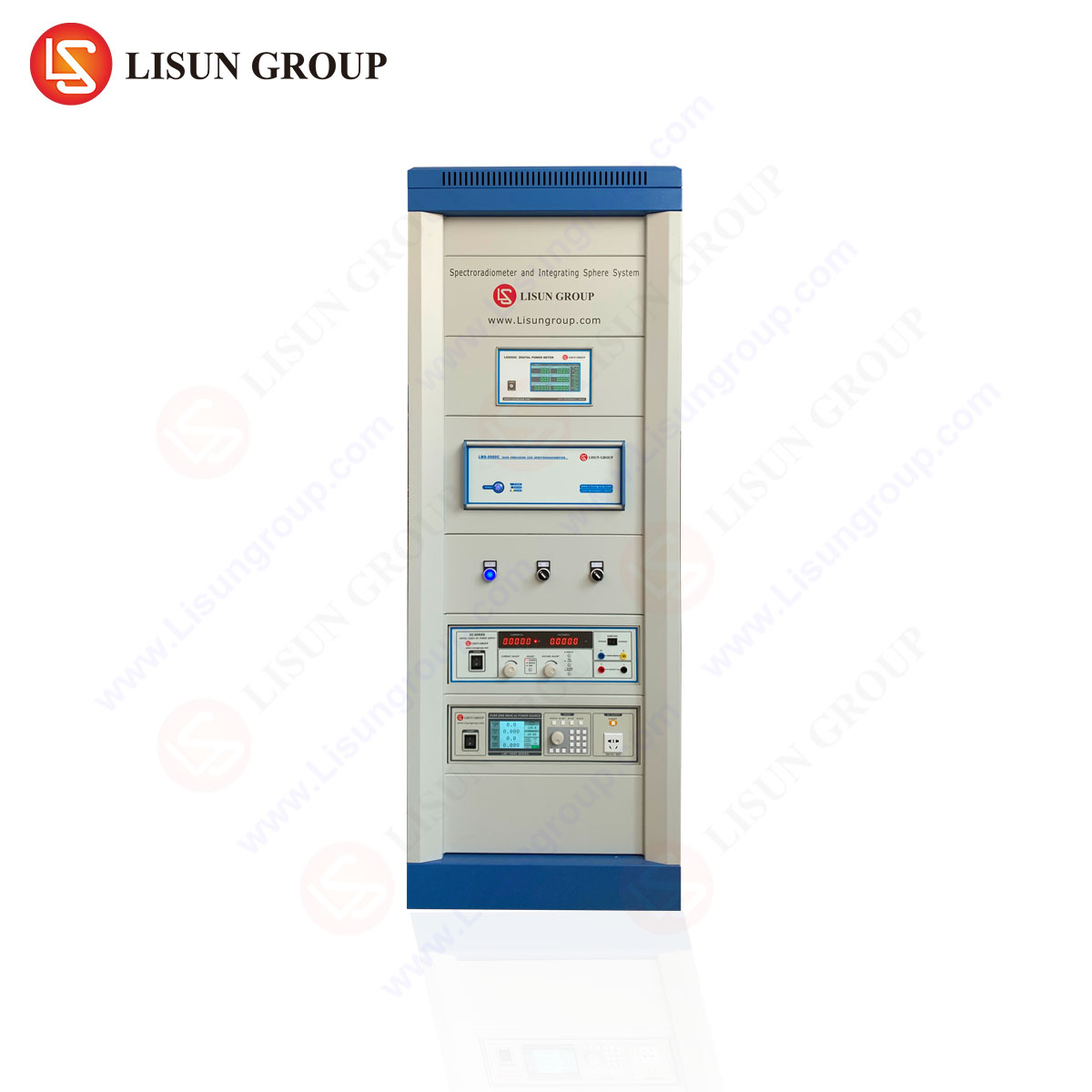
While manual C5 gauges are available for spot-checking, modern high-volume manufacturing and rigorous quality assurance protocols demand automated, repeatable, and data-driven testing. The LISUN Gauges for Plugs and Sockets represent a sophisticated integration of the core “go/no-go” principle into a fully automated test system. This system is engineered to perform a complete suite of mechanical tests as mandated by NF C 61-314, IEC 60884-1, and other related standards (e.g., BS 1363).
The LISUN system typically comprises a robust test station equipped with a multi-axis manipulator, a force sensor with high accuracy and resolution, a precision linear actuator, and a dedicated fixture for securing the socket-outlet under test. The system is controlled by specialized software that allows the operator to select the relevant test standard (e.g., NF C 61-314), configure test parameters (insertion force, speed, dwell time), and execute the sequence automatically.
Specifications of a typical LISUN Socket-Outlet Test System:
- Test Standards: Pre-programmed for NF C 61-314, IEC 60884-1, BS 1363, AS/NZS 3112, and more.
- Force Gauge Capacity: Typically 0 – 200 N, with an accuracy of ±0.5% full scale.
- Displacement Resolution: ≤ 0.01 mm.
- Test Probes: Manufactured from tool steel, hardened and ground, precisely matching the dimensions of the C5 and other required gauges (e.g., C6 for earth contacts).
- Actuator Speed: Programmable from 1 to 500 mm/min.
- Data Output: Detailed test reports including force-displacement curves, pass/fail status, and timestamped data for full traceability.
The Testing Protocol for Socket-Outlet Contacts
The automated testing process using the LISUN system involves a precise sequence of operations to evaluate the socket contacts. The socket-outlet is securely clamped in the test fixture. The system’s software identifies the test to be performed—for example, the NF C 61-314 C5 test for the phase and neutral contacts.
The manipulator aligns the “GO” gauge pin with the first socket contact. The linear actuator then advances the pin towards the contact at a controlled, standardized speed. The integrated force sensor continuously monitors the resistance. The pin must be inserted to its full depth with an insertion force below a maximum threshold defined by the standard. The system records the maximum force encountered during insertion.
Upon successful insertion, the pin is withdrawn. The manipulator then positions the “NO-GO” gauge pin. The actuator advances this pin with the same controlled motion. For the test to pass, the insertion force must exceed a minimum threshold before the pin reaches its forbidden depth, causing the system to halt the test and record a “NO-GO” condition. The software compares all measured values (forces, depths) against the pre-set tolerance windows from the standard and renders a definitive pass or fail verdict for each contact. This process is repeated for all relevant contacts (Phase, Neutral, Earth) on the socket-outlet.
Industry Applications and Competitive Advantages
The application of C5 gauge testing is mandatory within several critical industry segments. Manufacturers of plugs and socket-outlets integrate this testing into their Quality Control (QC) and Quality Assurance (QA) processes at incoming, in-process, and final inspection stages. It is a cornerstone of production line validation. Third-party certification bodies (e.g., those providing NF, CE, or Kitemark certification) rely on this testing to grant and maintain safety approvals. Retailers and importers utilize such testing as part of their due diligence to ensure products meet legal safety requirements before reaching consumers.
The LISUN Gauges for Plugs and Sockets system provides distinct competitive advantages over manual gauge testing:
- Elimination of Human Error: Automated systems apply consistent speed and alignment, removing variability introduced by different operators.
- Objective Data Recording: Instead of a subjective feel, the system generates quantitative, numerical data (exact force in Newtons) that can be stored, trended, and included in certification documents.
- Enhanced Throughput and Efficiency: Automated systems can test a complete socket-outlet in a fraction of the time required for manual testing, integrating seamlessly into high-speed production environments.
- Comprehensive Traceability: Every test result is digitally recorded with a timestamp and all relevant parameters, creating an immutable audit trail for quality management systems (ISO 9001) and regulatory compliance.
- Ergonomic and Operational Safety: Automating the repetitive application of force protects operators from potential strain injuries and ensures a safer laboratory environment.
Interpreting Force-Displacement Data for Quality Diagnostics
A key benefit of an automated system like LISUN’s is the ability to capture and analyze force-displacement curves. These curves are not merely for pass/fail determination; they are powerful diagnostic tools for the production process.
A typical successful “GO” test curve will show a smooth rise in force to a peak, followed by a drop as the gauge pin seats fully. An abnormally high peak force could indicate a issue with the spring contact’s geometry or surface finish, such as burrs or excessive plating. A jagged or erratic curve may suggest contamination or a poorly formed contact surface. Similarly, a “NO-GO” test that shows force building too slowly might indicate a worn or out-of-spec contact that is on the verge of failure, even if it technically passes the binary test at that moment. This granular data allows engineers to identify and rectify process issues long before they lead to a non-conforming product, moving from quality control to quality prediction and prevention.
Frequently Asked Questions (FAQ)
Q1: How frequently should the C5 gauge itself be calibrated?
The calibration interval for a precision gauge like the C5 depends on its frequency of use. For manual gauges used in a production environment, an annual calibration by an accredited laboratory against certified reference standards is recommended. For an automated system like the LISUN, the integrated force sensor and displacement actuator should undergo annual calibration, while the physical gauge pins should be periodically verified for dimensional wear.
Q2: Can the LISUN system test other aspects of a socket-outlet beyond dimensional checks?
Yes, a comprehensive LISUN test system is modular and can be equipped to perform a wide range of tests. This includes checking the shutters of child-safe sockets (e.g., the C7 gauge per NF C 61-314), measuring plug withdrawal force, testing the durability of switches (if present), and verifying the mechanical strength of the assembly. It is a unified platform for most mechanical tests required by the standard.
Q3: What is the consequence of a socket-outlet failing the C5 gauge test?
A failure indicates a critical non-conformity. The product must not be shipped or sold. The production batch should be isolated, and a root cause analysis initiated to identify the fault in the manufacturing process, such as a worn die, improper heat treatment of the contacts, or a fault in the assembly jig. Depending on the severity, a product recall of already distributed goods may be necessary.
Q4: Does the NF C 61-314 C5 gauge apply to all types of socket-outlets?
No. The C5 gauge is specifically designed for standard two-pole with earth (Type E/F) socket-outlets rated at 16A, 250V, as common in France and other European countries. Other plug types (e.g., UK BS 1363, Australian AS/NZS 3112) have their own distinct and non-interchangeable set of test gauges. The LISUN system is designed to accommodate these different gauge sets through interchangeable tooling.
Q5: How does temperature or humidity affect the test results?
The mechanical properties of the spring contacts can be slightly affected by temperature. The standards typically specify that testing should be conducted in a controlled laboratory environment (e.g., 23°C ± 5°C). The LISUN system provides objective data that is less susceptible to ambient condition variations than a human operator’s “feel,” but tests should still be performed in a stable environment for the most consistent and comparable results.