


Principles of Impact Resistance Evaluation via Spring Hammer Testing
The assessment of a product’s resilience to mechanical impacts is a critical component of its durability and safety validation. Among the standardized methodologies for this evaluation, spring hammer testing, governed primarily by IEC 60068-2-75 and other derivative standards, provides a controlled, reproducible means of simulating the stresses inflicted by accidental impacts during handling, service, or transportation. This non-destructive test is indispensable for verifying that enclosures, protective covers, and external components possess adequate mechanical strength to protect internal subsystems from damage.
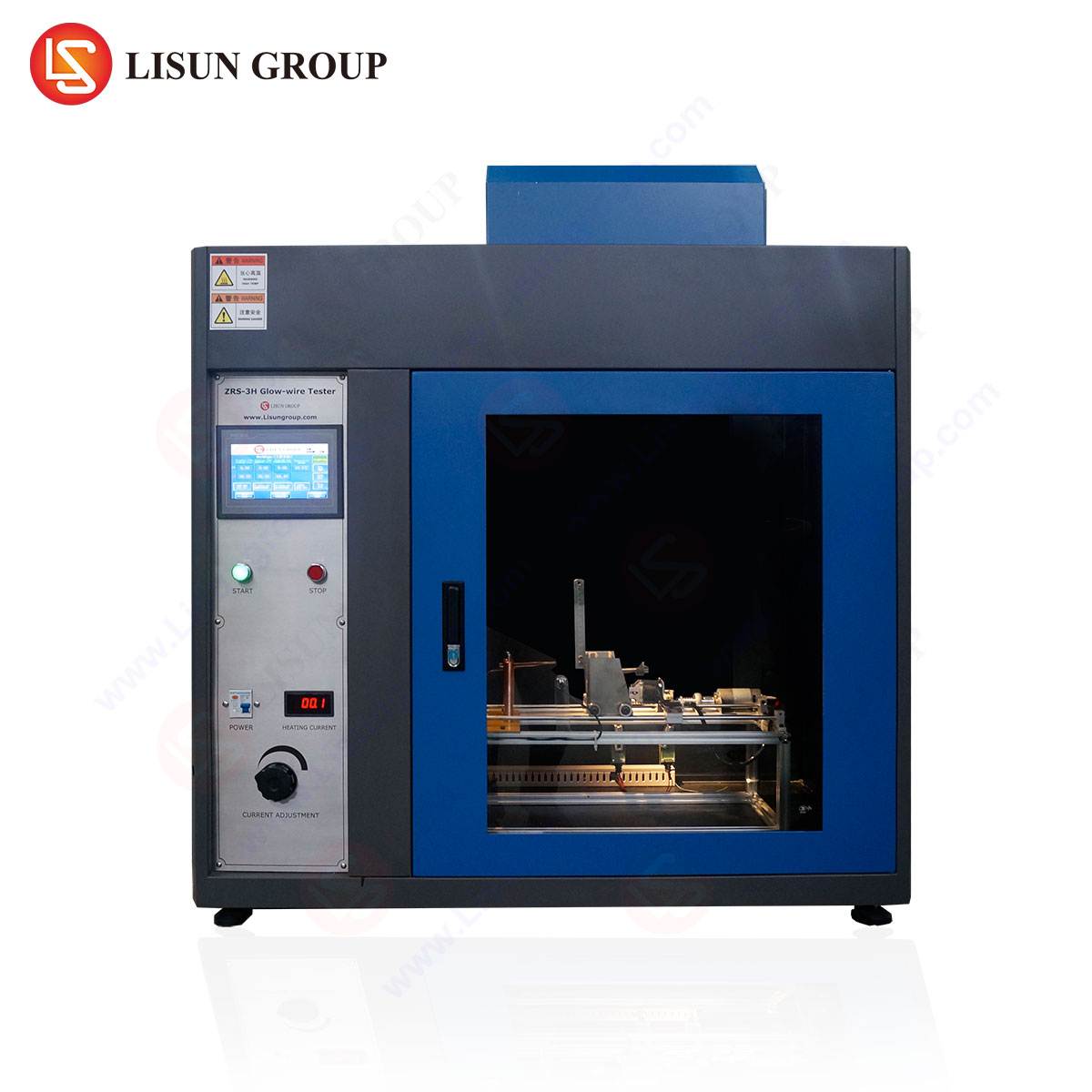
The fundamental operating principle of a spring hammer tester, or impact energy tester, involves the potential energy stored within a calibrated spring mechanism. This energy is converted into kinetic energy imparted to a hammer striker of specified mass and geometry upon release. The impact energy, measured in joules, is a function of the spring’s compression and is precisely defined by the standard for each test severity. The apparatus is designed to deliver impacts of consistent force and trajectory, eliminating operator-induced variables and ensuring repeatable results across laboratories and production batches. The test specimen is subjected to a prescribed number of impacts at designated points, after which it is inspected for cracks, fractures, deformation, or any compromise to its protective function, including verification of its IP rating for ingress protection.
Integration of Environmental Preconditioning with the HLST-500D Thermal Shock Test Chamber
The mechanical properties of materials, particularly polymers and composite resins used in enclosures, are profoundly influenced by their thermal history and operational temperature. A spring hammer test conducted solely at ambient temperature provides an incomplete assessment, as a component may perform adequately at 23°C but become brittle and fracture at -20°C or soften and deform at 70°C. To accurately simulate real-world conditions and identify these failure modes, specimens must be preconditioned to their operational thermal extremes prior to and during impact testing.
This is where the integration of a high-performance thermal shock test chamber becomes paramount. The LISUN HLST-500D thermal shock test chamber is engineered to subject products to extreme and rapid temperature transitions. Its specifications are critical for creating the necessary thermal stress states before mechanical impact.
HLST-500D Key Specifications:
- Temperature Range: -60°C to +150°C (extendable to -70°C or +180°C with optional upgrades)
- Temperature Recovery Time: ≤ 5 minutes (a critical metric for rapid cycling)
- Temperature Fluctuation: ±0.5°C
- Temperature Deviation: ±2.0°C
- Chamber Volume: 500 Liters (providing ample space for multiple test specimens or larger assemblies)
- Basket Switching Time: < 10 seconds (manual or automatic two-basket or three-basket systems available)
- Air Circulation: Forced air circulation within each zone to ensure temperature homogeneity.
The testing principle involves placing the test specimens into a basket within the HLST-500D chamber. The basket then automatically or manually transfers the samples between two or three independent zones: a high-temperature zone, a low-temperature zone, and an ambient zone if applicable. This subjects the specimens to severe thermal shock, inducing stresses that can reveal latent material flaws like microcracking or delamination. Following a defined number of cycles or after a specified dwell time at the target temperature, the specimens are transferred—often via a dedicated access port or quickly removed by the operator—for immediate impact testing with the spring hammer while still at the conditioned temperature.
Pre-Test Calibration and Apparatus Setup
Prior to any testing campaign, the spring hammer tester must be meticulously calibrated to ensure the accuracy of the impact energy. Calibration is typically performed using a dedicated proving device, which measures the actual energy delivered by the hammer impact. The steps involve mounting the proving device securely to a rigid base, cocking the spring hammer to the required energy level (e.g., 0.5 J, 0.7 J, 1.0 J, 2.0 J), and releasing the hammer to strike the anvil of the prover. The measured value on the prover must fall within the tolerance specified by the applicable standard (e.g., IEC 60068-2-75 mandates a tolerance of ±5%). Any deviation necessitates adjustment of the apparatus by a qualified technician.
The physical setup involves mounting the test specimen securely to a rigid, massive backing to prevent any energy absorption through movement or vibration. The standard specifies a minimum mass of 10 kg for the backing structure. The specimen must be mounted in its intended service orientation. The impact points are then selected based on the standard’s requirements, typically focusing on the most vulnerable areas: center points of surfaces, seams, joints, grilles, openings, and areas above internal components that are sensitive to shock. A template is often used to mark these points accurately.
Systematic Procedure for Conducting a Spring Hammer Test
The execution of the test follows a rigorous sequence to maintain consistency and validity.
- Specimen Identification and Conditioning: Identify the specimen and document its initial state. If thermal conditioning is required, place the specimen into the HLST-500D chamber and execute the predefined thermal shock or dwell profile. For a low-temperature impact test, a common profile would be a dwell at -25°C for a duration sufficient to thermally saturate the specimen (e.g., 2-4 hours depending on mass and material).
- Apparatus Preparation: Confirm the spring hammer is calibrated for the chosen impact energy level. Cock the hammer mechanism and secure it in the ready position.
- Specimen Mounting: Quickly transfer the thermally conditioned specimen from the HLST-500D chamber to its mounting fixture adjacent to the tester. It is crucial to minimize the time between removal from the chamber and impact application to prevent significant temperature change. For precise testing, some setups allow the spring hammer to act through a port into an environmental chamber.
- Application of Impacts: Align the spring hammer perpendicularly to the selected impact point on the test specimen. Release the hammer to deliver the impact. Repeat this for all pre-marked points on the specimen.
- Post-Impact Inspection: Following the test sequence, thoroughly inspect the specimen. Visual inspection is the first step, searching for any visible cracks, punctures, or permanent deformation exceeding permissible limits. This is often followed by a functional test. For enclosures intended to provide ingress protection, a dust or water spray test (IP5X or IPX4, for example) is conducted to verify that the impact has not compromised the sealing integrity.
- Documentation: Record all test parameters: impact energy, number of impacts, points of impact, preconditioning profile (including HLST-500D cycle data), environmental conditions during testing, and a detailed report of the post-test inspection findings.
Industry-Specific Applications and Use Cases
The combination of spring hammer and thermal shock testing is ubiquitous across industries where electronics and mechanical assemblies are exposed to harsh environments.
- Automotive Electronics: Control units (ECUs), sensors, and dashboard displays mounted in engine bays or on vehicle exteriors experience extreme temperature cycles and are vulnerable to impacts from road debris or tools during maintenance. Testing these components with the HLST-500D chamber to simulate under-hood temperatures followed by a 1J or 2J impact test is a standard validation procedure.
- Lighting Fixtures: Outdoor LED luminaires and automotive lighting must withstand thermal cycling from solar loading to cold nights while also being resistant to hail impact or vandalism. A 0.7J impact test on a lens preconditioned from 85°C to -40°C in the HLST-500D can validate its robustness.
- Medical Devices: Portable diagnostic equipment and handheld devices used in hospitals or ambulances are frequently subjected to accidental drops and impacts across a range of room temperatures. Testing ensures that casings do not shatter or open, preventing exposure to internal high-voltage components or compromising sterility.
- Telecommunications Equipment: Outdoor base station cabinets, fiber optic terminal boxes, and connectors are exposed to wide ambient temperature swings and must be robust against accidental impacts during installation or service. The HLST-500D’s rapid transition capability is ideal for simulating these conditions before impact testing.
- Aerospace and Aviation Components: Avionics bay components experience rapid decompression and temperature changes during ascent and descent. While requiring more specialized standards, the principle of thermal-mechanical stress testing is analogous, and the HLST-500D provides a ground-based means of validating material performance.
Analysis and Interpretation of Test Results
The outcome of a spring hammer test is not merely pass/fail. A detailed analysis of the failure mode provides invaluable data to design and materials engineers. A brittle fracture at a low temperature indicates a need for a material with a lower glass transition temperature or a redesigned geometry to reduce stress concentration. A ductile deformation or puncture at a high temperature suggests a need for a material with higher heat deflection temperature or greater impact strength.
The data gathered, especially when correlated with precise thermal preconditioning data from the HLST-500D, allows for the creation of material performance envelopes. This enables predictive modeling for future designs, reducing the time and cost of the development cycle. The objective evidence generated is also essential for obtaining safety certifications from bodies like UL, CSA, TÜV, and others.
Competitive Advantages of the Integrated HLST-500D Testing Solution
The LISUN HLST-500D thermal shock test chamber provides distinct advantages in a integrated testing regimen. Its rapid temperature recovery time and minimal deviation ensure that specimens are exposed to the precise thermal extreme for the required duration, eliminating a key source of test result variability. The large 500-liter volume accommodates not just multiple small components but also larger sub-assemblies like automotive ECU housings or industrial control panels, allowing for system-level testing. The robust construction and precise temperature control ensure reliability over thousands of test cycles, providing a high return on investment for quality assurance laboratories. When used in conjunction with a calibrated spring hammer tester, it creates a validation platform that thoroughly de-risks product design for real-world environmental and mechanical stresses.
Frequently Asked Questions
Q1: At what point in the product development cycle should spring hammer testing be integrated?
Spring hammer testing should be initiated during the prototyping phase. Identifying material or design weaknesses early allows for iterative improvements before final tooling is committed. It is also a critical part of the design validation (DVT) and production validation (PVT) phases to ensure consistent manufacturing quality.
Q2: How does the HLST-500D chamber’s switching time impact the test results?
A faster switching time, like the <10 seconds offered by the HLST-500D, minimizes the dwell time during the transition between extremes. This creates a more severe thermal shock condition, as the specimen has less time to equilibrate, thereby providing a more rigorous and conservative test that can uncover more subtle material defects.
Q3: Can the spring hammer test be automated?
While the standard methodology described is typically manual, automated systems exist for high-volume production testing. These systems use robotic arms to position the spring hammer and can integrate with environmental chambers for fully automated thermal-mechanical stress testing sequences.
Q4: What is the most common reason for test failure?
The most common failure is improper specimen mounting. If the specimen is not secured to a sufficiently massive and rigid backing, it will absorb impact energy through movement or vibration, yielding a false positive result. The second most common cause is the use of a non-calibrated or poorly maintained hammer tester.
Q5: Beyond the spring hammer, what other impact tests are used for electronic equipment?
The pendulum hammer (IEC 60068-2-75 Eh) for higher energy impacts and the drop test (IEC 60068-2-31) are also widely employed. The choice of test depends on the specific product standard and the type of impact hazard it is designed to withstand.