


Evaluating the Role of Walk-in Environmental Chambers in Product Qualification and Reliability Testing
The relentless pursuit of product reliability across a spectrum of industries necessitates rigorous simulation of operational environments long before deployment. While benchtop chambers serve for component-level assessment, the verification of full-scale assemblies, large sub-systems, and complete products demands a more substantial testing platform. The walk-in environmental chamber represents the apex of this capability, providing a controlled, room-sized volume in which temperature, humidity, and other climatic variables can be precisely manipulated to accelerate aging, identify design flaws, and validate performance under stipulated conditions. These chambers are indispensable for ensuring that products ranging from automotive electronic control units to entire telecommunications cabinets can withstand the thermal and hygroscopic stresses encountered throughout their lifecycle.
Architectural and Operational Principles of Walk-in Chambers
The fundamental architecture of a walk-in environmental chamber is predicated on creating a thermally insulated, hermetically sealed enclosure integrated with a robust conditioning system. Unlike smaller chambers, the scale introduces unique engineering challenges centered on spatial uniformity and temporal stability of the environmental parameters. The structure itself is typically composed of modular panels featuring a core of high-density polyurethane or fiberglass insulation sandwiched between stainless steel or aluminum cladding. This construction minimizes thermal bridging and ensures energy efficiency. A critical component is the access door, which employs a sophisticated gasketing mechanism to maintain an airtight seal under internal pressure and thermal contraction/expansion cycles.
The conditioning system is a centralized apparatus, often located adjacent to or atop the test volume. It comprises several key subsystems: a refrigeration circuit for cooling and dehumidification, electric heaters for heating, a humidification system (commonly steam injection or atomizing types), and a high-capacity air circulation system. The refrigeration unit typically operates on a cascade or compound refrigeration principle to achieve wide temperature ranges, especially for sub-ambient conditions. Air is continuously circulated from the conditioning unit through a plenum and directed into the test space via strategically placed diffusers. The return air, laden with the thermal and moisture load from the test specimens, is drawn back into the system for re-conditioning. This closed-loop cycle is governed by a programmable controller that modulates the various actuators—compressors, heaters, and humidifiers—based on feedback from precision sensors distributed within the workspace. The primary objective is to achieve and maintain the setpoint conditions with minimal deviation, a metric defined as temperature and humidity uniformity.
Integrating Benchtop Chamber Data for System-Level Validation
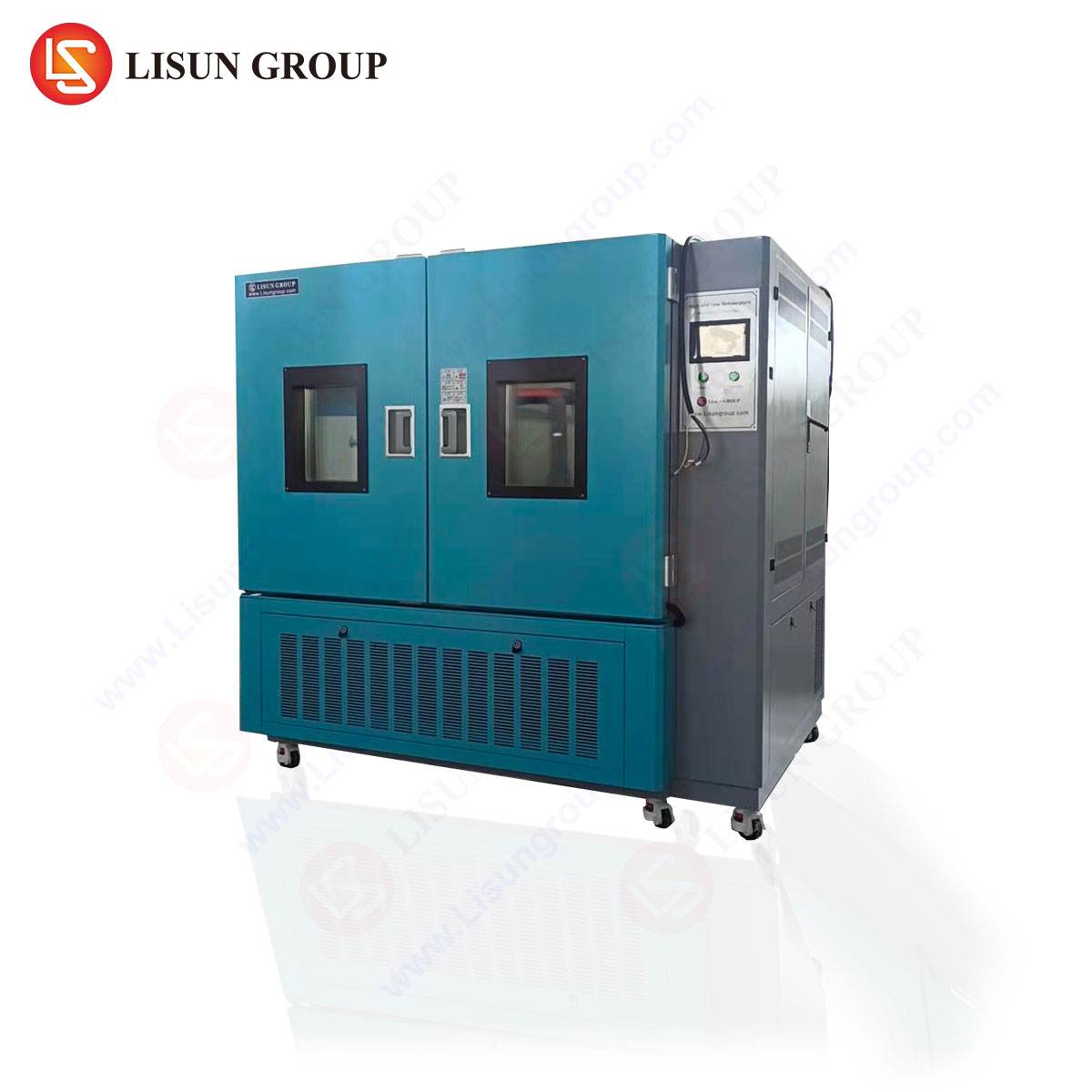
The efficacy of a comprehensive testing regimen often relies on a pyramid approach, where component-level testing informs and precedes system-level validation. Data derived from precise, high-performance benchtop chambers are critical for qualifying individual elements before they are integrated into a larger assembly for walk-in chamber testing. For instance, the performance parameters of a specific integrated circuit, validated in a unit like the LISUN GDJS-015B Temperature Humidity Test Chamber, provide a baseline for understanding its behavior before it is mounted on a printed circuit board and subjected to system-level stresses.
The LISUN GDJS-015B exemplifies the type of equipment used for this foundational testing. Its specifications are engineered for precision and repeatability at a component level. It typically offers a temperature range of -70°C to +150°C, with a humidity range of 20% to 98% RH. The rate of temperature change can be a critical factor, with models like the GDJS-015B capable of rapid ramping, often exceeding 3°C per minute across certain portions of its range. This allows for accelerated thermal cycling, uncovering latent defects in solder joints, substrates, and semiconductor packages. The chamber’s operational principles involve a sophisticated balance between its refrigeration coil for dehumidification and cooling, and its electric immersion heater for both heating the air and generating steam for humidification. A forced-air circulation system ensures the stipulated uniformity, which is typically within ±0.5°C for temperature and ±2.5% for humidity. By subjecting electrical components—such as microcontrollers, memory modules, or RF amplifiers—to these controlled stresses, engineers can screen for infant mortality failures and characterize performance limits. This data is indispensable when the same components are later part of a complex system inside a walk-in chamber, as it helps isolate whether a system-level failure originates from a component flaw or a system-integration issue (e.g., thermal crosstalk, inadequate airflow).
Simulating Real-World Environmental Stress for Large Assemblies
The primary justification for employing a walk-in chamber is the physical scale of the unit under test (UUT). Industries such as automotive, aerospace, and telecommunications routinely produce assemblies that are simply too large for any conventional benchtop chamber. An automotive engineer, for example, may need to validate the performance of an entire vehicle’s infotainment system, climate control module, and advanced driver-assistance system (ADAS) computer simultaneously under cold-start conditions at -40°C. Similarly, a manufacturer of industrial control systems must certify that a full programmable logic controller (PLC) cabinet, complete with power supplies, communication modules, and I/O blocks, operates flawlessly in a factory environment with high ambient temperatures and fluctuating humidity.
The test protocols executed within these chambers are often dictated by international standards. For electrical and electronic equipment, standards such as IEC 60068-2-1 (cold), IEC 60068-2-2 (dry heat), and IEC 60068-2-30 (damp heat, cyclic) provide standardized procedures for environmental testing. A walk-in chamber enables the execution of these standards on a grand scale. A typical test profile might involve a 24-hour stabilization period at 85°C and 85% relative humidity—a standard damp heat test for accelerated life testing—followed by a functional check of all systems. For lighting fixture manufacturers, this could mean testing entire luminaire arrays to ensure that thermal management, driver electronics, and optical integrity are maintained over extended periods. The chamber’s ability to maintain strict uniformity is paramount here; a gradient of just a few degrees across a large UUT could lead to misleading results, with one part of the assembly passing while another fails.
The Criticality of Thermal Shock Testing in Conjunction with Steady-State Profiles
While steady-state temperature and humidity testing are vital for assessing long-term reliability, many field failures occur due to rapid transitions between extreme conditions. The thermal expansion coefficients of dissimilar materials—such as ceramic substrates, copper traces, plastic housings, and solder alloys—can induce significant mechanical stress during such transitions, leading to cracked components, delamination, and solder joint fatigue. This failure mode is specifically addressed by thermal shock testing, a discipline that demands specialized equipment separate from, yet complementary to, the walk-in chamber.
The LISUN HLST-500D Thermal Shock Test Chamber is designed to apply this specific, severe form of stress. Its testing principle revolves around the rapid transfer of a test specimen between two independently controlled temperature zones: one hot and one cold. The HLST-500D, for instance, typically features a high-temperature zone ranging from +60°C to +200°C and a low-temperature zone from -10°C to -65°C. The transition time, a critical performance metric, is often specified as less than 10 seconds. This rapid transfer subjects the UUT to extreme thermal strain rates that are not replicable in a standard walk-in chamber, which has a much larger thermal mass and thus a slower ramp rate.
The synergy between the two types of testing is a cornerstone of a robust qualification program. A batch of automotive electronics might first undergo thermal shock testing in an HLST-500D to weed out units with manufacturing defects in the solder or substrate. The surviving units could then be integrated into a full vehicle subsystem and placed inside a walk-in chamber for a prolonged temperature-humidity bias test. This sequential approach efficiently identifies different failure mechanisms. For example, a medical device like a patient monitor may pass a steady-state operational test at a high temperature but fail during a thermal shock cycle due to a micro-crack in a ball grid array (BGA) package that propagates with each rapid temperature change.
Quantifying Performance: Data Acquisition and Analysis
The value of environmental testing is unlocked not merely by the application of stress but by the meticulous acquisition and analysis of performance data from the UUT. A walk-in chamber test is therefore an instrumented endeavor. Data loggers and sensor arrays are placed on and within the test specimen to monitor critical parameters: internal temperatures of power semiconductors, voltage outputs from switching power supplies, signal integrity from communication buses, and physical parameters like deformation or condensation.
Modern walk-in chambers are equipped with sophisticated control and monitoring systems that log the chamber’s environmental conditions alongside this UUT data. This synchronized data stream allows for powerful correlation analysis. An engineer can determine, for instance, if a failure in an aerospace component’s communication link is directly correlated with a specific low-temperature threshold or a spike in humidity. The use of reference standards, such as those published by the International Organization for Standardization (ISO) or Underwriters Laboratories (UL), provides the acceptance criteria against which this data is judged. A table summarizing common tests and their applicable standards is illustrative:
| Test Type | Typical Standard | Applicable Industry | Key Parameter Ranges |
|---|---|---|---|
| Damp Heat, Steady State | IEC 60068-2-78 | Automotive Electronics, Telecom | +25°C to +85°C, 85% RH |
| Cold Operational Test | IEC 60068-2-1 | Aerospace, Consumer Electronics | -40°C to -65°C |
| Thermal Shock (Air-to-Air) | IEC 60068-2-14 | Electrical Components, Medical Devices | -65°C to +150°C, <10s transfer |
| Temperature Cycling | IEC 60068-2-14 | Lighting Fixtures, Office Equipment | -40°C to +125°C, 3°C/min ramp |
This quantitative approach transforms subjective assessment into an objective, data-driven decision-making process for product release, design modification, or supplier qualification.
Addressing Industry-Specific Application Challenges
The application of walk-in chambers is tailored to the unique failure modes and operational environments of different sectors. In the automotive electronics industry, tests often simulate the extreme thermal inertia of a vehicle sitting in desert sun followed by a cold-soak overnight, requiring prolonged exposure to high temperatures and subsequent cold-start cycles. For telecommunications equipment, such as a 5G baseband unit, the focus may be on continuous operation at high ambient temperatures (e.g., +55°C) with high internal heat loads, testing the efficacy of its cooling solution. The chamber must be able to handle this significant heat dissipation from the UUT, a factor that is often negligible in smaller-scale testing.
In medical devices, regulatory compliance dictated by standards like ISO 13485 necessitates exhaustive documentation of environmental testing protocols. A walk-in chamber might be used to validate the storage and transport stability of a large imaging device like an MRI console or to ensure that an automated DNA analyzer functions correctly in the varying climates of a global market. For cable and wiring systems, the chamber can accommodate large reels of cable to perform thermal aging tests, measuring the degradation of insulation and jacketing materials over time at elevated temperatures. In each case, the chamber is not merely a climate simulator but a critical tool for mitigating financial, safety, and reputational risk by uncovering latent vulnerabilities in a controlled laboratory setting.
Frequently Asked Questions (FAQ)
Q1: What is the primary distinction between a temperature humidity chamber like the GDJS-015B and a thermal shock chamber like the HLST-500D?
The fundamental distinction lies in the rate and method of temperature application. The GDJS-015B provides controlled, often gradual, ramping between temperature and humidity setpoints, suitable for steady-state dwells and cyclic tests. The HLST-500D is designed for extreme, rapid transitions, instantly moving the test specimen between separate hot and cold zones to induce mechanical stress from thermal expansion mismatch. They uncover different failure mechanisms and are often used sequentially in a test plan.
Q2: How is temperature uniformity guaranteed across the vast volume of a walk-in chamber?
Uniformity is a function of the chamber’s air handling system. It is achieved through careful engineering of the airflow pattern, using a combination of high-capacity blowers, strategically placed supply diffusers, and return air vents. The goal is to create a consistent, turbulent mix of air throughout the workspace, minimizing stagnant pockets. The specified uniformity (e.g., ±2.0°C) is validated during commissioning by mapping the space with a multi-sensor array.
Q3: When validating a large product, is it necessary to test every single component individually in a benchtop chamber first?
While not always feasible for every component, it is a highly recommended best practice for critical components. Testing high-risk or new components (e.g., a custom ASIC, a new power module) in a benchtop chamber like the GDJS-015B first isolates their performance and failure modes. This de-risks the subsequent, more expensive system-level test in the walk-in chamber, as engineers can distinguish between a component failure and a system-level integration issue (e.g., poor board layout, insufficient cooling).
Q4: What are the key safety protocols when testing high-voltage or power-dense equipment in a walk-in chamber?
Safety is paramount. Protocols typically include independent emergency stop buttons inside and outside the chamber, interlock systems that cut power to the UUT if the chamber door is opened, and robust chamber construction with fire-retardant materials. For high-power devices, the chamber’s electrical feed-throughs must be rated for the expected current and voltage. Continuous monitoring of UUT parameters and internal chamber conditions is essential to detect anomalies like overheating before they become hazardous.