


A Technical Examination of Pin Gauge Testing Standards Under UL 498: Ensuring Safety and Interoperability in Plugs and Receptacles
Introduction
The global ecosystem of electrical plugs and receptacles is governed by a complex framework of dimensional and performance standards designed to ensure safety, reliability, and interoperability. At the core of this framework for North American devices is UL 498, the Standard for Safety for Attachment Plugs and Receptacles. Compliance with UL 498 is not merely a regulatory hurdle; it is a fundamental requirement for market access and a critical safeguard against electrical hazards such as shock, fire, and equipment damage. Among the most precise and non-negotiable verification methods mandated by this standard is pin gauge testing—a metrological procedure that validates the critical dimensions of plug blades and receptacle contacts. This article provides a detailed technical analysis of UL 498 pin gauge testing, its underlying principles, and its indispensable role in the manufacturing and quality assurance processes for plugs and sockets. The discussion will incorporate the application of specialized test equipment, such as the LISUN Gauges for Plugs and Sockets, to illustrate the practical execution of these rigorous standards.
The Foundational Role of Dimensional Compliance in UL 498
UL 498 establishes comprehensive requirements for the construction, performance, and testing of attachment plugs, receptacles, and similar wiring devices intended for connection to branch circuits. While the standard addresses a wide array of criteria—including temperature rise, dielectric withstand, and endurance cycling—dimensional compliance forms the foundational layer of safety. Precise blade and contact geometry is essential for several interrelated safety outcomes. First, it ensures proper electrical engagement: blades must mate with receptacle contacts with sufficient contact pressure to minimize resistance and subsequent overheating under load. Second, it prevents the insertion of plugs into receptacles of incorrect voltage or current rating, a critical aspect of polarization and configuration. Third, it mitigates the risk of shock by ensuring that live parts are not accessible during partial insertion or withdrawal. Pin gauge testing is the primary quantitative method for verifying that manufactured components adhere to the specified dimensional tolerances outlined in UL 498, particularly in clauses governing blade thickness, width, length, and spacing.
Metrological Principles of Pin Gauge Verification
Pin gauge testing operates on the principle of “go/no-go” or limit gauging. This method utilizes precision-machined gauges designed to the maximum and minimum material limits specified by the standard. A “go” gauge, sized to the minimum acceptable opening or maximum acceptable pin dimension, must fit under a defined force. Conversely, a “no-go” gauge, sized to the maximum acceptable opening or minimum acceptable pin dimension, must not fit. This binary assessment provides a rapid, unambiguous determination of dimensional compliance without the need for interpretive measurement from variable instruments like calipers.
The application of this principle within UL 498 is multifaceted. For receptacle testing, a series of pin gauges are used to verify the contact slot dimensions. A gauge representing the maximum blade thickness must enter the slot to a specified depth, confirming the slot is not too narrow. A separate gauge representing the minimum blade thickness must not enter, confirming the slot is not too wide, which would result in poor contact pressure. Similarly, plug blades are verified using slot gauges or dimension-specific templates. The standard prescribes exact forces for gauge insertion (typically measured in newtons) to eliminate operator variability and ensure that the test simulates real-world mating forces. This methodology directly assesses the functional interoperability of the mating pair, transcending simple dimensional measurement to evaluate performance-critical parameters.
Critical Test Parameters and Gauge Specifications for Blades and Contacts
The specific dimensional attributes verified by pin gauges are derived from the detailed tables and diagrams within UL 498. These include, but are not limited to:
- Blade Thickness and Width: For flat parallel blades (NEMA 1-15, 5-15, etc.), gauges verify that blade thickness falls within the allowed range (e.g., 0.062–0.068 inches for a standard 15A blade). Width is similarly checked to ensure proper alignment and current-carrying surface area.
- Blade Length and Profile: The length of the current-carrying and grounding blades is critical for sequencing of connection and disconnection. Gauges ensure the grounding pin of a plug is the longest, guaranteeing it makes first and breaks last.
- Blade Spacing (Center-to-Center): The distance between blade centers is rigorously controlled. Incorrect spacing can prevent insertion into a standardized receptacle or cause misalignment that leads to arcing or high contact resistance.
- Receptacle Contact Slot Dimensions: The internal dimensions of the receptacle contacts are gauged to ensure they will accept the corresponding “go” blade gauge but reject the “no-go” gauge, confirming the spring tension and contact geometry are correct.
- Polarization and Rejection Features: For polarized and grounded configurations, gauges verify the unique shapes and sizes that prevent incorrect insertion (e.g., ensuring a NEMA 5-15P plug cannot be forced into a NEMA 1-15R receptacle).
The gauges themselves are manufactured from hardened tool steel or other durable materials to resist wear from repeated use. Their surface finish, geometric accuracy, and hardness are calibrated to national standards (e.g., NIST in the United States) to ensure traceability and long-term reliability. A complete test set for a given configuration, such as the NEMA 5-15, will include multiple individual gauges for each of these critical parameters.
Implementation in Quality Assurance: Laboratory and Production Floor Applications
In a manufacturing environment, pin gauge testing is deployed at multiple control points. Incoming quality inspection (IQC) uses gauges to validate components from suppliers, such as stamped blade assemblies or molded receptacle bodies. During in-process quality control (IPQC), operators or automated systems perform gauge checks at specified intervals, often after critical stamping, molding, or assembly stations. Finally, finished product audit (FPA) involves a comprehensive gauge check on random samples from completed batches prior to shipment.
The efficiency of the go/no-go method allows for high-frequency testing without requiring highly skilled metrologists for every check. This integration into the production flow creates a statistical process control (SPC) dataset, where trends in gauge fit can indicate tooling wear in stamping dies or mold degradation before non-conforming products are produced. For certification laboratories and third-party test houses, pin gauge tests are the first objective checks performed on submitted samples. Failure to pass these dimensional tests often precludes further, more complex performance testing, as the fundamental safety premise of the design is not met.
Case Study: The LISUN Gauges for Plugs and Sockets System
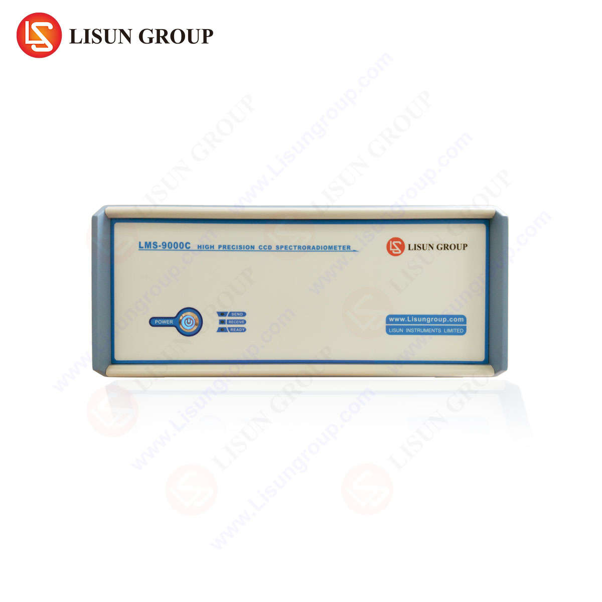
To exemplify the application of these standards, we can examine the LISUN Gauges for Plugs and Sockets. This system embodies the technical requirements of UL 498 and other international standards (like IEC 60884) in a calibrated, traceable toolset. A typical LISUN set for NEMA configurations includes a structured array of gauges, each serving a distinct verification function.
Specifications and Design Principles: LISUN gauges are precision-engineered from high-carbon chromium steel, heat-treated to a hardness of HRC 58-62 to ensure exceptional wear resistance and dimensional stability over thousands of cycles. The gauges feature a ground and lapped finish with precise chamfers to facilitate correct entry into test slots without binding. Each gauge is clearly marked with its designated function (e.g., “MIN BLADE THK” or “GROUND PIN GO”) and the relevant standard clause. The sets are supplied with a calibration certificate traceable to national metrology institutes, which is a mandatory requirement for audits by certification bodies like UL, Intertek, or CSA.
Testing Protocol Execution: Using the LISUN system, a technician follows a regimented procedure. For a 125V 15A receptacle (NEMA 5-15R), the test sequence might be:
- Contact Slot Width: Insert the “GO” gauge for hot/neutral slot width. It should enter fully under its own weight or a specified minimal force.
- Contact Slot Thickness: Insert the “GO” blade thickness gauge. It must enter. Attempt to insert the “NO-GO” thickness gauge. It must not enter.
- Grounding Contact: Verify the U-shaped grounding contact using a cylindrical “GO” gauge for diameter and a “NO-GO” gauge to ensure sufficient grip.
- Polarization: Verify that the wider neutral slot will not accept the narrower “hot” blade gauge, ensuring proper polarization.
A similar, complementary process is used for plug blades. The use of a unified, organized set like LISUN’s minimizes operator error and ensures all required checks are performed consistently.
Industry Use Cases and Competitive Advantages in Device Manufacturing
The primary users of such gauge systems are wiring device manufacturers, third-party testing laboratories, and large-scale purchasers who perform incoming inspection. The competitive advantages of a dedicated, high-quality gauge system are significant. First, it reduces compliance risk by providing tools with verified accuracy, directly mitigating the risk of shipping non-compliant products that could lead to recalls, liability, or decertification. Second, it enhances production efficiency by enabling fast, definitive checks that keep pace with production line speeds, unlike slower, variable manual measurements. Third, it improves product quality and consistency by providing immediate feedback on tooling wear, allowing for predictive maintenance before tolerances are exceeded. Finally, it streamlines the certification process, as testing laboratories themselves use similar gauge sets; providing data from a traceable system like LISUN can expedite sample validation during initial product certification or follow-up surveillance audits.
Correlation Between Dimensional Accuracy and Electrical Performance
It is a technical imperative to understand that pin gauge testing is not an isolated dimensional exercise. The parameters it verifies have a direct and quantifiable impact on electrical performance tests mandated later in UL 498. For instance:
- Contact Pressure (from blade thickness/slot width): Directly influences contact resistance. Excessive resistance leads to localized heating, failing temperature rise tests (Clause 9) and potentially causing premature failure in endurance cycling (Clause 7).
- Blade Engagement Length: Affects the current-carrying path. Insufficient engagement can create a high-resistance point, leading to overheating and failure during abnormal overload tests (Clause 13).
- Polarization Integrity: Prevents the miswiring of devices, which is a primary safety function tested under fault conditions.
Therefore, successful pin gauge verification is a strong predictor of success in subsequent, more resource-intensive electrical tests. It is the first and most cost-effective gate in a series of safety validations.
Maintenance, Calibration, and Traceability of Pin Gauge Sets
The integrity of the pin gauge testing process is wholly dependent on the maintained accuracy of the gauges themselves. Daily use, even with hardened steel, leads to gradual wear, particularly on “GO” gauges which are in sliding contact with test pieces. A formal calibration schedule is mandatory. Industry best practice dictates annual recalibration by an accredited laboratory, with more frequent user checks against a master gauge set reserved for verification only.
Proper handling and storage are equally crucial. Gauges must be kept in their protective cases when not in use to prevent nicks or corrosion. They should be handled with clean gloves to avoid acidic contamination from skin oils. The concept of metrological traceability is paramount: each gauge’s calibration certificate must document an unbroken chain of comparisons to higher-order standards, ultimately leading to a national measurement institute. This traceability is a non-negotiable requirement during audits by any accredited certification body, ensuring that the “go/no-go” decision is rooted in internationally recognized measurement certainty.
Conclusion
Pin gauge testing under UL 498 represents a critical convergence of mechanical metrology and electrical safety engineering. Its implementation through precision tool sets, such as the LISUN Gauges for Plugs and Sockets, provides the manufacturing and testing industries with an objective, reliable, and efficient method to validate the foundational safety geometry of plugs and receptacles. By ensuring strict adherence to dimensional tolerances, this process directly prevents electrical hazards, guarantees interoperability, and forms the essential first step in a comprehensive safety certification protocol. As wiring devices evolve and standards are updated, the role of precise, traceable dimensional verification will remain a constant and indispensable pillar of product safety and reliability.
Frequently Asked Questions (FAQ)
Q1: How often should a set of pin gauges like the LISUN system be recalibrated in an active production environment?
A: For gauges in daily use within a manufacturing quality control setting, an annual recalibration cycle by an ISO/IEC 17025 accredited laboratory is the industry standard. However, intermediate checks using a certified master gauge set should be performed quarterly or monthly, depending on usage volume, to detect accelerated wear. Any gauge that is dropped or damaged must be removed from service and recalibrated immediately.
Q2: Can one gauge set be used to test both plugs and receptacles for a given NEMA configuration?
A: Yes, a comprehensive set like those offered by LISUN is designed as a complete system for a given configuration. It will include specific gauges for plug blade verification (e.g., thickness templates, spacing gauges) and separate, complementary gauges for receptacle contact slot verification. The set is engineered to test the mating pair against the same dimensional limits, ensuring interoperability.
Q3: What is the consequence of using a “GO” gauge that has become worn below its minimum limit?
A: A worn “GO” gauge is undersized. It will pass components that are themselves at or below the minimum material limit, meaning it will accept blades that are too thin or slots that are too narrow. This is a critical failure mode, as it could allow products with insufficient contact pressure (from thin blades in normal slots) to pass inspection, leading to potential overheating hazards in the field. This underscores the necessity of regular calibration.
Q4: Are there specific environmental conditions required for performing UL 498 pin gauge tests?
A: While not as stringent as for electronic calibration, standard laboratory conditions (room temperature of 20°C ±5°C, relative humidity below 80%) are recommended. Most importantly, the gauges and the devices under test should be acclimatized to the same ambient temperature to avoid measurement error due to thermal expansion of the metal components. The test surface should be clean, well-lit, and free of debris that could affect gauge insertion.