


Technical Specifications and Operational Principles of Environmental Thermal Chambers for Reliability Validation
Environmental thermal chambers constitute a critical infrastructure component within the product development and validation lifecycle for a diverse array of industries. These precision instruments simulate extreme climatic and thermal conditions, enabling engineers to assess product durability, functional integrity, and long-term reliability under accelerated stress. The data derived from such testing protocols is indispensable for mitigating field failure risks, ensuring regulatory compliance, and substantiating product warranties. This technical treatise delineates the core specifications, operational methodologies, and application paradigms for these chambers, with a focused examination on thermal shock testing as exemplified by the LISUN HLST-500D thermal shock test chamber.
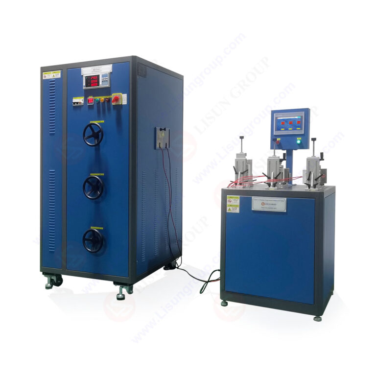
Fundamental Architecture and Thermodynamic Systems
The foundational architecture of an environmental chamber is predicated on achieving and maintaining precise thermal and hygrometric conditions within an insulated workspace. Key subsystems include the insulated test compartment, a refrigeration circuit, a heating assembly, a humidification system (for combined temperature-humidity models), and a sophisticated digital controller. The test compartment, typically constructed from stainless steel, incorporates low-thermal-conductivity insulation to minimize thermal leakage and ensure energy efficiency. The refrigeration system, often a cascade or single-stage compressor configuration, is responsible for heat extraction to achieve sub-ambient and cryogenic temperatures. Conversely, resistive heating elements provide the necessary thermal energy for elevated temperature setpoints. In chambers designed for humidity simulation, a boiler generates steam for humidification, while the refrigeration coil facilitates dehumidification through condensation. The precise orchestration of these conflicting systems—simultaneous heating and cooling, or humidifying and dehumidifying—is managed by a programmable controller utilizing PID (Proportional-Integral-Derivative) algorithms to ensure minimal deviation from the target profile.
The Regime of Thermal Shock Testing: Principles and Implementation
Thermal shock testing represents a more severe and specialized validation discipline compared to steady-state temperature cycling. Its objective is to evaluate a test specimen’s resilience to rapid, extreme transitions between high and low temperature extremes. This test regime is particularly relevant for identifying latent material defects, such as micro-cracks in solder joints, delamination of composite structures, or failure of adhesive bonds, which may not be revealed through gradual thermal changes. The principle exploits differential coefficients of thermal expansion (CTE) among dissimilar materials within an assembly. A rapid temperature transition induces mechanical stress at material interfaces; repetitive cycling accelerates fatigue, leading to identifiable failures.
The LISUN HLST-500D thermal shock test chamber implements a two-zone (also known as a two-basket) methodology to execute this testing. The unit comprises three primary chambers: a high-temperature zone, a low-temperature zone, and a transition basket or elevator that holds the test specimens. The specimen basket automatically shuttles between the pre-conditioned high and low temperature chambers with minimal transfer time, typically under 10 seconds, thereby subjecting the products to an instantaneous thermal transition. This design is superior to single-chamber methods, as both extreme zones remain at constant, stable setpoints, eliminating the lag and energy expenditure associated with ramping a single chamber between extremes.
Detailed Analysis of the HLST-500D Thermal Shock Test Chamber
The HLST-500D is engineered for rigorous compliance with standards such as IEC 60068-2-14 (Test N: Change of temperature) and MIL-STD-202G. Its specifications are tailored for high-throughput, reliable shock testing.
Key Technical Specifications:
- Test Volume: 500 Liters.
- Temperature Range: High Temperature Chamber: +60°C to +150°C; Low Temperature Chamber: -10°C to -55°C (extendable to -65°C with optional LN2 boost).
- Recovery Time: ≤5 minutes to reach extreme setpoints from ambient after specimen transfer.
- Transition Time: <10 seconds (mechanical transfer between zones).
- Temperature Fluctuation: ±0.5°C.
- Temperature Uniformity: ±2.0°C.
- Basket Load Capacity: 30 kg.
- Controller: Digital programmable touchscreen controller with data logging and USB interface for profile programming and result export.
- Safety Features: Independent overtemperature protection, compressor delay protection, phase failure protection, and chamber door interlocks.
Operational Workflow: A test profile is programmed specifying dwell times at high and low temperatures and the number of cycles. The HLST-500D pre-conditions both zones. The basket, loaded with specimens, begins in one zone. Upon completing the dwell, the basket rapidly transfers to the opposite zone. This cycle repeats automatically, with the controller monitoring and recording chamber temperatures throughout.
Industry-Specific Application Contexts
The deployment of thermal shock chambers like the HLST-500D is pervasive across sectors where electronic or mechanical components face harsh environmental service conditions.
- Automotive Electronics: Components such as Engine Control Units (ECUs), sensors, and infotainment systems must endure temperature swings from under-hood heat to winter cold. Thermal shock testing validates solder joint integrity in printed circuit board assemblies (PCBAs) and the sealing effectiveness of enclosures.
- Aerospace and Aviation Components: Avionics, satellite modules, and communication equipment encounter rapid temperature shifts during ascent/descent or orbital transitions. Testing here focuses on preventing catastrophic failure due to material contraction/expansion.
- Telecommunications Equipment: 5G outdoor units, base station amplifiers, and fiber optic transceivers are exposed to diurnal and seasonal temperature variations. Shock testing ensures signal integrity and physical durability.
- Lighting Fixtures: LED drivers and outdoor luminaires are subjected to thermal shock from internal heat generation coupled with external cold rain or snow, testing the resilience of thermal interface materials and housing seals.
- Medical Devices: Portable diagnostic equipment and implantable device components must maintain functionality after sterilization (high heat) and subsequent storage. Testing validates material stability and electronic reliability.
- Electrical Components & Wiring Systems: Connectors, switches, and cable insulation are tested for cracking, embrittlement, or loss of dielectric properties after repeated shock cycles.
Comparative Advantages in Engineering Design
The HLST-500D embodies several design features that confer operational and data integrity advantages. Its dual-station independent air circulation system within each zone ensures exceptional temperature uniformity and rapid recovery post-transfer, a critical factor for maintaining the specified dwell time severity. The use of a mechanical lift transfer mechanism, as opposed to pneumatic systems, offers higher load capacity (30kg) and enhanced long-term mechanical reliability with less maintenance. The programmable controller allows for complex cycling profiles, including pre-conditioning soaks and user-defined transition sequences, facilitating simulation of real-world scenarios beyond simple two-point cycling. Furthermore, its construction with high-grade insulation and robust sealing minimizes thermal cross-talk between zones and reduces overall energy consumption during sustained operation.
Standards Compliance and Testing Protocol Development
Adherence to international test standards is non-negotiable for cross-border market acceptance. Thermal shock testing is governed by several key standards, each with nuanced requirements. IEC 60068-2-14 details test methods for component and equipment, defining parameters like severity (temperature extremes), dwell duration (typically until thermal stability is reached), and number of cycles. MIL-STD-202G, Method 107, is a prevalent military standard defining rigorous thermal shock procedures for electronic components. Automotive manufacturers often impose even stricter proprietary standards, such as those from the Automotive Electronics Council (AEC-Q100). A chamber like the HLST-500D must not only be capable of achieving the physical parameters but also provide the traceability and documentation—via its data logging system—to prove compliance during audit processes. Effective protocol development involves correlating the accelerated laboratory test conditions (e.g., 100 cycles from -40°C to +125°C) with predicted field lifetime under real-world thermal fatigue conditions.
Data Acquisition, Interpretation, and Failure Analysis
The endpoint of testing is not merely the completion of cycles but the analysis of results. Chambers are integrated with monitoring systems to record internal chamber conditions. However, critical test data often comes from monitoring the specimens under test (DUTs). This requires routing power and signal cables into the chamber to perform in-situ functional testing during dwell periods—a feature supported by the HLST-500D via feed-through ports. Failure analysis post-test is crucial. A component failing thermal shock may exhibit a cracked ceramic capacitor, fractured solder joint (visible under X-ray or microscope), intermittent electrical connectivity, or compromised waterproofing. Correlating the cycle count at failure with the physical failure mode provides actionable intelligence for redesign, such as selecting components with matched CTEs, improving PCB layout, or modifying assembly processes.
Integration into Broader Reliability Testing Ecosystems
A thermal shock chamber is rarely an island. It functions within a broader reliability testing ecosystem that may include steady-state temperature/humidity chambers, vibration test systems, salt spray cabinets, and combined environmental stress screening (ESS) chambers. The sequence of testing is strategic. For instance, thermal shock might precede vibration testing to induce micro-cracks that subsequently propagate under mechanical stress, or follow humidity testing to assess the impact of moisture ingress during thermal cycling. The data from the HLST-500D contributes to a larger reliability growth model, informing Failure Modes, Effects, and Criticality Analysis (FMECA) and enabling quantitative reliability predictions like Mean Time Between Failures (MTBF).
Frequently Asked Questions (FAQ)
Q1: What is the critical distinction between temperature cycling and thermal shock testing?
A1: The primary distinction is the rate of temperature change. Temperature cycling involves controlled ramps (e.g., 3°C/min) between extremes, stressing materials more gradually. Thermal shock features nearly instantaneous transfers (seconds) between pre-conditioned hot and cold zones, inducing greater mechanical stress due to the high thermal gradient, making it more effective at uncovering assembly and workmanship flaws.
Q2: How is the appropriate dwell time determined for a thermal shock test?
A2: Dwell time is not arbitrary. Per standards like IEC 60068-2-14, the dwell should be sufficient for the test specimen to reach thermal stability throughout its mass. This is often determined empirically by monitoring the temperature of a dummy load or the slowest-to-respond part of the actual product until its internal temperature stabilizes within a few degrees of the chamber air temperature. It is not synonymous with chamber recovery time.
Q3: Can the HLST-500D accommodate in-situ (live) electrical testing of components during the cycle?
A3: Yes, this is a critical capability. The chamber is equipped with electrical feed-through ports that allow for power and signal cables to be connected to the specimens inside the basket. This enables continuous or intermittent functional testing during the dwell periods at high and low temperatures, allowing for the detection of intermittent failures that may only occur at a specific temperature extreme.
Q4: What maintenance is paramount for ensuring the long-term accuracy and reliability of a thermal shock chamber?
A4: Regular preventive maintenance is essential. Key tasks include: cleaning condensers and filters to maintain refrigeration efficiency, checking and calibrating temperature sensors (typically annually), inspecting door seals for integrity to prevent thermal leakage, verifying the mechanical operation and alignment of the transfer basket, and ensuring the lubricant in the compressor system is within specification. A log of all maintenance and calibrations should be kept for quality audits.
Q5: For a product destined for global markets, which standard should be referenced for thermal shock testing?
A5: A comprehensive validation strategy often references multiple standards. IEC 60068-2-14 is a widely accepted international baseline. For automotive electronics, AEC-Q100 is typically mandated. For aerospace or military applications, MIL-STD-202G or RTCA DO-160 may be required. The most stringent applicable standard from the target market should be selected, and the chamber must be capable of meeting its specific parametric requirements (temperature range, transfer rate, recovery time).