


Technical Evaluation of the 100mm Test Pin with Integrated Cable for Hazardous Part Accessibility Assessment
Introduction to Accessibility Probe Verification in Product Safety Engineering
Within the framework of product safety engineering, the verification of protection against access to hazardous parts constitutes a foundational compliance activity. This process is not merely a procedural checkpoint but a critical risk-mitigation exercise mandated by international safety standards. The objective is to empirically determine whether a hazardous live part, a moving component, or a high-temperature surface within an enclosure is accessible to a human user—or, more specifically, to a standardized representation of a human body part. The integrity of this determination hinges entirely on the precision and conformity of the test equipment employed. The LISUN Test Finger, Test Probe, Test Pin series embodies this principle, with the
100mm Pin with Cable serving as a specialized instrument for evaluating access to hazardous live parts and mechanical hazards through small openings. Its design and application are governed by a strict regime of dimensional tolerances, material properties, and procedural protocols derived from standards such as IEC 61032, IEC 60529 (IP Code), and UL 60950-1, now largely integrated into the IEC 62368-1 hazard-based safety standard.
This technical article provides a comprehensive analysis of the
100mm Pin with Cable, detailing its specifications, operational principles, and indispensable role across diverse manufacturing sectors. The discourse will remain strictly objective, focusing on the instrument’s function as a metrological tool for validating safety barriers in electrical and electronic equipment.
Dimensional and Material Specifications of the
100mm Test Pin
The
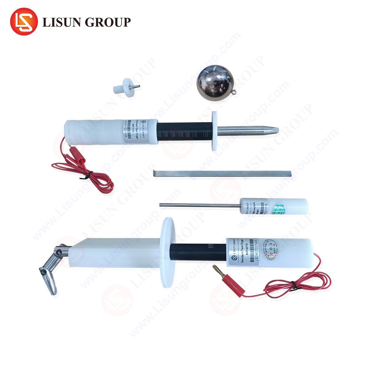
100mm Pin with Cable is defined by a set of exacting physical parameters. Its primary function—to simulate access through openings that may permit contact with hazardous parts—demands unwavering geometric consistency.
The probe itself is a cylindrical rod with a nominal length of 100 millimeters (±0.1 mm tolerance). The critical dimension is its diameter, standardized at 1.0 mm (±0.02 mm). This specific diameter is not arbitrary; it is calibrated to represent a minimal opening through which a rigid object, akin to a straightened paperclip or a small tool fragment, could be inserted. The tip of the pin is hemispherical with a radius of 0.5 mm, ensuring no sharp edges that could inadvertently damage insulation or gaskets during testing, which would constitute an invalid test condition.
The pin is constructed from hardened, non-corrosive steel, providing the necessary rigidity to maintain its form under a defined test force without bending or flexing that could compromise the test. The surface finish is typically polished to a specified roughness to prevent snagging and ensure smooth insertion. The pin is permanently affixed to an insulated handle or a cable termination. In the cabled variant, the cable length is typically 1 meter, composed of flexible, durable insulation capable of withstanding repeated use and storage. The connection between the pin and the cable is a point of mechanical reinforcement to prevent failure at the stress point.
A fundamental accessory to the probe is the test force apparatus. The standard mandates the application of a 1 Newton (±0.1 N) force axially to the pin. This is often achieved via a calibrated spring mechanism or a dead-weight system integrated into the test station. Applying excessive force can invalidate the test by deforming the equipment under test (EUT) in an unrealistic manner, while insufficient force may not fully simulate the potential for user probing.
Table 1: Primary Technical Specifications of the
100mm Pin with Cable
| Parameter | Specification | Tolerance | Reference Standard |
| :— | :— | :— | :— |
| Pin Length | 100 mm | ±0.1 mm | IEC 61032, Figure 5 |
| Pin Diameter | 1.0 mm | ±0.02 mm | IEC 61032, Figure 5 |
| Tip Geometry | Hemispherical | Radius 0.5 mm | IEC 61032 |
| Material | Hardened Steel | – | Common practice |
| Test Force | 1 N | ±0.1 N | IEC 61032, Clause 6 |
| Cable Length | 1000 mm | – | Typical configuration |
| Insulation Resistance | >100 MΩ (handle/cable) | @ 500 V DC | Safety requirement |
Electromechanical Testing Principles and Procedural Protocol
The operational principle of the
100mm Pin with Cable is rooted in a binary, fail-safe detection methodology. The test is designed to answer a single, critical question: Can the probe make electrical or mechanical contact with a part deemed hazardous?
The procedural protocol is systematic. First, the Equipment Under Test (EUT) is placed in its most unfavorable configuration for access—doors open, covers removed as intended by the user, adjustable parts positioned to maximize opening size. The
100mm Pin is then connected to a detection circuit. This circuit is typically a low-voltage (e.g., 40-50V) source in series with a current-limiting resistor and an indicator lamp or audible buzzer. The pin forms one pole of the circuit; the other pole is connected to all accessible conductive parts of the EUT and, crucially, to the hazardous live parts inside it.
The test engineer applies the specified 1 N force and attempts to insert the pin into every opening, grille, vent, gap, or joint in the enclosure. The pin is manipulated through all possible angles of approach. If the pin contacts a hazardous live part, it completes the detection circuit, illuminating the indicator. This constitutes a test failure, demonstrating that the product’s construction does not adequately protect against the specified hazard. The test also assesses mechanical hazards; contact with moving parts like fans or gears is observed directly.
It is vital to distinguish this from the LISUN Test Finger (articulated jointed finger, simulating a child’s finger) and the Test Probe (typically a 3mm diameter probe for higher energy hazards). The
100mm Pin addresses a distinct, smaller-scale access hazard. A comprehensive safety evaluation requires a toolkit of these complementary probes, applied in a hierarchy defined by the standard.
Cross-Industry Application in Safety Compliance Verification
The universality of the access hazard makes the
100mm Pin with Cable a ubiquitous tool in the compliance laboratories of virtually every sector manufacturing physical products.
- Electrical and Electronic Equipment & Industrial Control Systems: Here, the probe verifies that live busbars, terminal blocks, PCB-mounted components, and relay contacts within industrial cabinets, PLC housings, and power supplies are inaccessible through ventilation slots or assembly seams.
- Household Appliances and Consumer Electronics: It tests openings in food processors, power tool housings, charger adapters, and set-top boxes to ensure user cannot probe and contact mains-voltage connections or motor terminals.
- Automotive Electronics: With the proliferation of in-vehicle infotainment, control units, and charging systems, the pin checks for accessibility to 12V/48V or high-voltage traction battery connections within component housings, mitigating risk during servicing or accidental damage.
- Lighting Fixtures: For both indoor and outdoor luminaires, the probe is used to test gaps in housing assemblies and cable entry points to prevent contact with the LED driver’s live parts or the lamp holder terminals.
- Telecommunications Equipment: Data center switches, routers, and base station units are tested to ensure safety for installation and maintenance personnel, verifying that slots and vents do not permit access to backplane power connections.
- Medical Devices: Patient safety is paramount. The pin tests enclosures of bedside monitors, infusion pumps, and diagnostic equipment to guarantee that even with a small, rigid object, no hazardous voltage is accessible from outside the intended patient or operator interfaces.
- Aerospace and Aviation Components: In this high-reliability sector, the probe validates the integrity of enclosures for in-flight entertainment systems, navigation avionics, and cabin control panels, ensuring no safety compromise from tiny openings.
- Electrical Components: For switches, sockets, and connectors, the test verifies that live pins or contacts cannot be touched through any opening when the component is in a partially engaged or “resting” state.
- Cable and Wiring Systems: The probe may be used to test access through the gland entries of junction boxes or cable conduits.
- Toy and Children’s Products Industry: While the Test Finger is primary for simulating finger access, the
100mm Pin
is critical for testing battery compartments and any openings that could allow a child to insert a rigid wire or similar object, potentially leading to short circuits or access to small, ingestible parts.
Metrological Advantages and Compliance Assurance
The competitive advantage of a precisely manufactured tool like the LISUN
100mm Pin with Cable lies in its role as a source of compliance assurance and risk reduction. Its value is derived from several key attributes.
Foremost is dimensional fidelity. Compliance testing is a legal and technical benchmark. A probe with out-of-spec diameter or tip geometry can yield false negatives (passing an unsafe product) or false positives (failing a safe product), both of which carry severe consequences—product liability, recall costs, or unnecessary design changes. The strict adherence to IEC 61032 Fig. 5 specifications ensures test results are reproducible and defensible.
Material durability and construction integrity are equally critical. The hardened steel resists deformation, ensuring the 1.0 mm diameter is maintained over thousands of test cycles. The robust cable and termination prevent breakage, which could leave probe fragments in an EUT or necessitate frequent, costly recalibration and replacement.
Furthermore, the ergonomic and functional design of the complete LISUN Test Finger, Test Probe, Test Pin ecosystem facilitates efficient testing. The clear, reliable indication circuit, the comfortable grip, and the organized presentation of the toolset reduce operator error and fatigue, increasing throughput in a compliance lab environment without sacrificing accuracy.
Ultimately, the instrument provides traceable verification. Using a certified, standardized probe allows a manufacturer to generate test reports that reference an unambiguous, internationally recognized tool. This documentation is essential for obtaining safety marks (UL, CE, CCC, etc.), passing audits by certification bodies (e.g., TÜV, Intertek), and providing evidence of due diligence in product safety engineering.
Integration within a Holistic Hazard-Based Safety Framework
It is imperative to contextualize the use of the
100mm Pin. It is not a standalone solution but a single, precisely defined instrument within a broader hazard-based safety engineering process as outlined in IEC 62368-1. This standard moves from prescriptive rules to a philosophy of identifying energy sources (electrical, thermal, kinetic) and prescribing safeguards against them.
The probe is a tool for verifying the effectiveness of a “physical safeguard”—specifically, an “enclosure” or “insulation barrier.” Its application follows a risk assessment. The designer first identifies potential hazardous parts. Then, appropriate safeguards are engineered. The
100mm Pin is the empirical tool used to validate that the engineered safeguard (e.g., a vent with an internal baffle, a sealed joint, a reinforced insulating sleeve) performs as intended under the simulated condition of probing with a rigid wire. Its use is often sequential: after verifying that a larger opening is protected by a Test Finger, smaller openings are scrutinized with the Test Probe and finally the
100mm Pin to ensure a comprehensive defense-in-depth strategy.
Frequently Asked Questions (FAQ)
Q1: What is the fundamental difference between the LISUN Test Finger, the Test Probe, and the
100mm Test Pin?
A1: They simulate different access scenarios. The articulated Test Finger (roughly 12mm diameter) simulates a child’s finger testing for basic access. The Test Probe (typically 3mm diameter) simulates a tool or object for testing access to higher-energy hazardous parts. The
100mm Pin (1.0mm diameter) is for evaluating access through very small openings that could be penetrated by a rigid wire or similar slender object, addressing a distinct, finer level of hazard.
Q2: Can a product fail a safety test based solely on the
100mm Pin test?
A2: Absolutely. If the pin, under 1 N of force, can contact a hazardous live part or a dangerous moving component through any opening on the enclosure, the product fails to comply with the relevant clause of the safety standard (e.g., IEC 62368-1, Clause 8.5.2). This failure indicates an immediate safety risk that must be addressed through redesign, such as adding internal barriers, reducing opening sizes, or improving insulation.
Q3: How often should a
100mm Pin with Cable be calibrated or verified?
A3: While there is no universal mandated interval, best practice in an accredited laboratory (ISO/IEC 17025) dictates periodic verification. This should occur at least annually, or more frequently if the tool is subject to heavy use or any mechanical impact. Verification involves checking the critical dimensions (diameter, length, tip radius) with calibrated micrometers and optical comparators, and testing the electrical continuity and insulation of the cable/handle.
Q4: Is the 1 Newton test force critical, and how is it applied consistently?
A4: The force is a critical parameter. Applying more force can deform flexible materials or displace components, creating an unrealistic access path and causing a false failure. Applying less force may not simulate a realistic probing action. Consistency is achieved using a calibrated force gauge or a dedicated test apparatus that limits the axial force applied to the pin to 1 N ±0.1 N, ensuring repeatable and standardized test conditions.
Q5: For a plastic enclosure with flexible vents, how is the test conducted to ensure validity?
A5: This is a nuanced scenario. The standard often requires testing in the “most unfavorable position.” The flexible vent may be manually deformed or held open to its widest foreseeable extent during normal use or assembly. The pin is then applied without exceeding the 1 N force. The test aims to simulate what a user could reasonably do, not to destroy the enclosure with excessive force. The judgment of “reasonable” force is guided by the standard’s specifications and often requires engineering judgment documented in the test procedure.