


The 10N Thrust Test Probe: A Foundational Instrument for Hazard-Based Safety Evaluation
Introduction to Hazard-Based Safety Compliance
The global regulatory framework governing the safety of electrical and electronic equipment is predicated on a fundamental principle: the prevention of accessible hazardous live parts. This principle transcends individual industries, forming the bedrock of standards such as IEC 61032, IEC 60529 (IP Code), UL 60950-1, and their myriad national derivatives. Compliance verification necessitates not merely visual inspection but quantifiable, reproducible mechanical testing that simulates real-world interaction. The 10N Thrust Test Probe, exemplified by instruments like the LISUN Test Finger, Test Probe, and Test Pin, serves as this critical simulation tool. It is a calibrated apparatus designed to apply a standardized force to evaluate the effectiveness of enclosures, openings, and protective barriers against accidental contact by human body parts, typically fingers or hands. This article provides a comprehensive technical examination of the 10N Thrust Test Probe, its operational principles, specifications, and its indispensable role across diverse technological sectors.
Mechanical and Dimensional Specifications of Standardized Probes
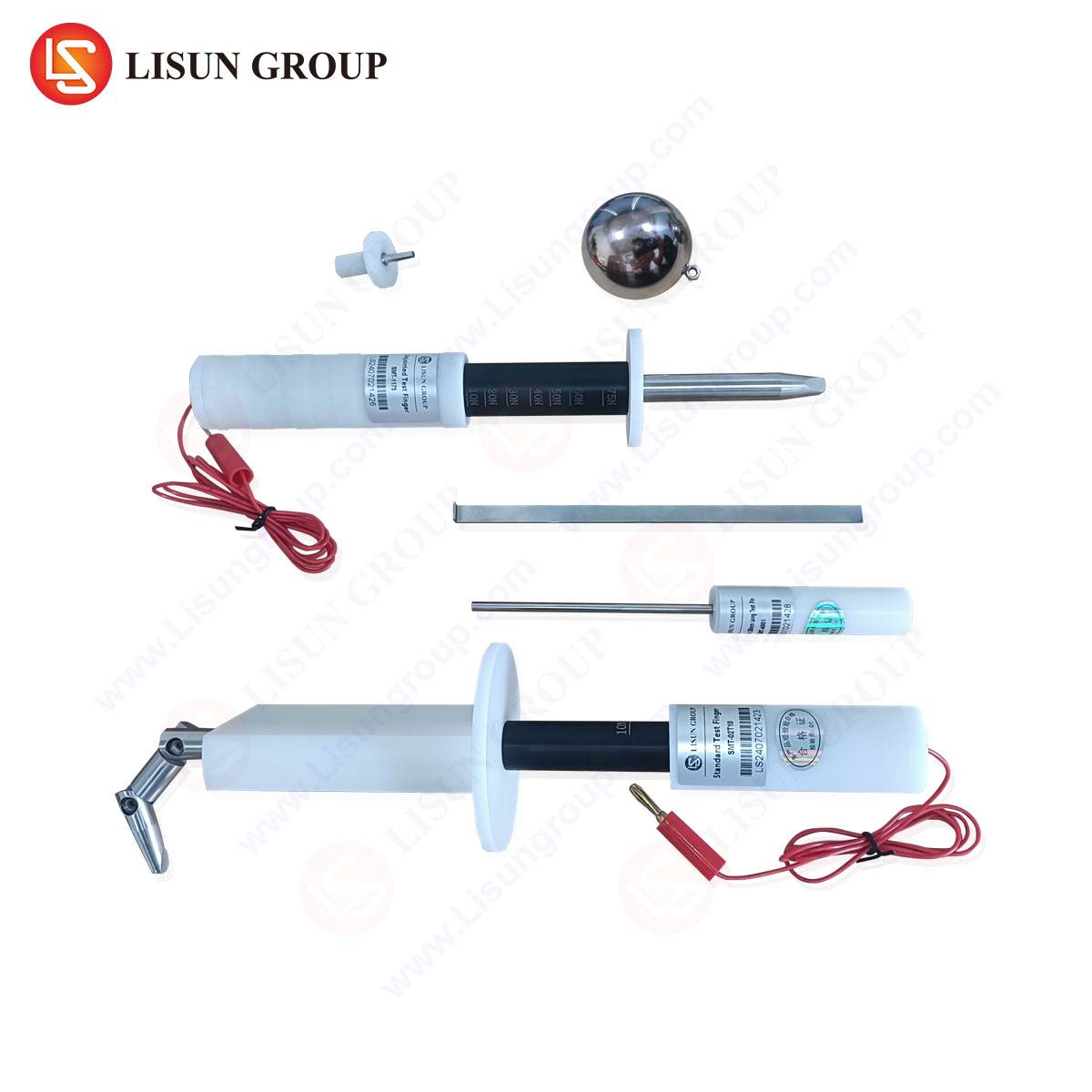
The efficacy of a safety test probe is contingent upon its strict adherence to dimensional and mechanical tolerances as defined in international standards. The probe is not a generic pin but a precisely engineered instrument. The classic “test finger” or “jointed test finger,” as per IEC 61032 Figure 2 (Test Probe B), simulates the dimensions of a small child’s finger or an adult’s distal phalanx. Its typical specification includes a diameter of 12mm, a length of 80mm for the distal section, and a three-jointed design allowing for articulation to simulate natural probing motion. The complementary “test pin” (IEC 61032 Figure 1, Test Probe 13) is a rigid, unjointed probe with a 3mm diameter, designed to assess protection against access by tools or wires.
The defining characteristic of the 10N Thrust Test Probe is its integrated or applied force mechanism. The “10N” designation refers to the Newton force applied axially during testing—approximately equivalent to 1.02 kilograms-force. This force is applied without shock to the probe, which is then articulated or moved to attempt contact with live parts. Probes like the LISUN series are manufactured from insulating materials, often stainless steel with insulated sleeves, to prevent electrical conductivity that could invalidate the test. The tip is radiused to a specified dimension (e.g., 20mm radius for the test finger) to prevent sharp edges from compromising the enclosure during testing.
Table 1: Common Test Probe Specifications per IEC 61032
| Probe Type | Standard Reference | Typical Dimensions | Applied Force | Simulated Object |
| :— | :— | :— | :— | :— |
| Jointed Test Finger | Figure 2 (Probe B) | Ø12mm, 80mm length, 3 joints | 10N ± 10% | Finger/hand |
| Test Pin | Figure 1 (Probe 13) | Ø3mm, length variable | 1N ± 10% | Tool, wire |
| Sphere Probe | Figure 3 (Probe 41) | Ø12.5mm sphere | 30N ± 10% | Hand-held object |
Operational Principles and Testing Methodology
The testing procedure utilizing a 10N Thrust Test Probe is a systematic hazard assessment. The equipment under test (EUT) is de-energized for initial setup, though the test itself often evaluates the clearance distance to live parts that would be energized in normal use. The probe is attached to a force gauge or a calibrated spring mechanism ensuring the 10N force is maintained. The probe is then deliberately inserted into every opening, gap, vent, or joint in the equipment’s enclosure. This includes openings formed by removable parts, between knobs and panels, and at cable entry points.
During insertion, the articulated test finger is manipulated through its full range of motion—typically up to 90° from the axial line in any direction—to simulate a finger exploring an opening. The critical pass/fail criterion is unambiguous: the probe must not contact any hazardous live part or uninsulated moving part (like a fan blade). Furthermore, for IP rating tests (IEC 60529), the probe’s ability to penetrate an opening defines the “protection against access to hazardous parts” digit (the first digit of the IP code). A successful test demonstrates that the product’s physical design provides a fundamental level of operational safety under foreseeable conditions of use, including curiosity-driven probing by children.
Cross-Industry Application and Use Cases
The universality of the accessible hazardous parts hazard makes the 10N Thrust Test Probe a ubiquitous tool in compliance laboratories across the industrial spectrum.
Electrical and Electronic Equipment & Household Appliances: This is the primary domain. For a kitchen blender, the test finger is applied around the base seal, button interfaces, and any ventilation slots to ensure fingers cannot contact the motor assembly or internal wiring. Food processors, electric kettles, and washing machine control panels all undergo this scrutiny.
Automotive Electronics: As vehicles incorporate more user-accessible infotainment systems, charging ports (e.g., USB-C, 12V sockets), and control switches, protection against finger ingress is vital. Testing ensures that a passenger cannot accidentally contact the low-voltage DC bus bars or connector terminals behind a seemingly closed panel.
Lighting Fixtures: Recessed lighting, street lamps, and household luminaires have openings for heat dissipation and wiring. The probe verifies that fingers cannot reach live lamp terminals or the LED driver’s internal components, even when reaching through a broken diffuser.
Industrial Control Systems and Telecommunications Equipment: PLC cabinets, server racks, and router chassis are tested at access panels, cooling fan grilles, and cable pass-through glands. The goal is to protect service technicians from accidental contact with mains terminals or high-current DC distribution while performing routine maintenance.
Medical Devices: Patient safety is paramount. Devices like dialysis machines, patient monitors, and imaging equipment must prevent access to internal high-voltage sections (e.g., in X-ray generators or ultrasound power supplies) via control panel gaps or service doors, even when a caregiver is cleaning the device or a patient is interacting with it.
Aerospace and Aviation Components: In-flight entertainment systems, cockpit control panels, and galley equipment are subject to rigorous environmental and safety testing. The thrust probe ensures durability and safety, verifying that vibration or panel flexure does not create an access path to hazardous voltages.
Electrical Components: This is a critical application. Switches, sockets, circuit breakers, and connector housings are designed with specific “touch-proof” features. The test pin and test finger are used to verify that a finger cannot make contact with live contacts in a partially inserted plug or when a switch is in an intermediate position.
Cable and Wiring Systems: For cable glands, conduit entries, and connectorized systems, the probe tests the effectiveness of the strain relief and sealing mechanism in preventing access to the conductors if a cable is pulled or twisted.
Toy and Children’s Products Industry: Given the intended user, standards (like IEC 62115) impose stricter requirements. The 10N probe is used aggressively on battery compartments, seams of electronic toys, and charging ports to ensure absolute protection against access to battery terminals or internal circuits, mitigating risks of burns or electrical shock.
The LISUN Test Probe Series: Precision in Compliance Verification
Within the ecosystem of compliance testing equipment, the LISUN Test Finger, Test Probe, and Test Pin product line embodies the necessary precision for accredited laboratory work. These instruments are manufactured to meet the exacting dimensional requirements outlined in IEC 61032, UL 60950-1, and other regional standards. Their construction from durable, dimensionally stable materials ensures longevity and consistent performance, preventing calibration drift that could arise from wear or deformation of the probe tip or joints.
The competitive advantage of a dedicated, calibrated probe system lies in its reproducibility and auditability. Using a non-compliant, improvised tool introduces unacceptable variables. The LISUN probes provide traceable calibration certificates, documenting that their dimensions and the applied force mechanism (whether integrated or when used with a calibrated force gauge) are within the ±10% tolerance mandated by the standards. This traceability is non-negotiable for manufacturers seeking certification from bodies like TÜV, UL, or Intertek, as it forms the objective basis for the test report. Furthermore, the availability of a full set of probes (finger, pin, sphere) allows a single laboratory to assess a product against multiple hazard scenarios, streamlining the compliance process for complex products that may be evaluated under several standards.
Standards Integration and Regulatory Significance
The 10N Thrust Test Probe is not an optional tool but a mandatory interface between product design and regulatory acceptance. Its use is explicitly prescribed. For instance:
- IEC 62368-1 (Audio/Video, Information & Communication Technology Equipment): Clause 6.2.2 specifies the use of the jointed test probe to verify protection against access to hazardous energy sources.
- IEC 60335-1 (Household Appliances): Clause 8.1.1 and 22.11 require the test finger to check for adequate protection against contact with live parts and moving parts.
- IEC 60598-1 (Luminaires): Clause 8.2.1 references IEC 61032 for testing protection against electric shock.
The test results directly feed into the product’s Technical Construction File (TCF) and are a focal point during certification audits. A failure—where the probe contacts a live part—necessitates a redesign, often involving increased creepage/clearance distances, improved enclosure interlocking, or the addition of internal barriers. Thus, the probe acts as a crucial feedback mechanism in the design-for-safety (DfS) iterative process.
Limitations and Complementary Test Methodologies
It is critical to recognize the scope and limitations of the 10N Thrust Test Probe. It simulates a specific, albeit common, hazard. It does not assess protection against:
- Ingress of solids or liquids (IP Rating): While related, full IP testing involves separate dust chambers and water spray nozzles.
- Resistance to impact: Mechanical strength is tested with impact hammers (e.g., IEC 60068-2-75).
- Hazards from very small objects: Protection against access by wires or tools is the domain of the test pin (1N force) or other specialized probes.
- Long-term durability: It is a type-test, not a test of wear-and-tear over the product’s lifetime.
Therefore, the 10N probe is one instrument in a comprehensive safety testing suite. A complete safety evaluation will sequentially apply impact tests, ingress protection tests, and then the probe test, as earlier tests may create new openings to be evaluated.
Conclusion
The 10N Thrust Test Probe represents a deceptively simple yet profoundly important concept in product safety engineering: the quantifiable simulation of human interaction. By providing a standardized, repeatable method to assess the fundamental risk of accessible hazardous parts, it serves as a universal benchmark. Instruments like the LISUN Test Finger series translate abstract standard clauses into actionable, physical verification. Their consistent and correct application across industries—from children’s toys to aerospace controls—ensures that the baseline expectation of user protection is met, forming an indispensable link in the global chain of product safety, risk mitigation, and regulatory compliance. As product forms evolve and new human-device interfaces emerge, the principle embodied by this test will remain constant, even as the specific probes and standards continue to be refined.
Frequently Asked Questions (FAQ)
Q1: Can a 10N Thrust Test Probe be used for both IP rating testing and electric shock hazard testing?
Yes, but for different aspects. The first digit of the IP code (e.g., IP2X) specifically uses the jointed test finger to denote “protection against access to hazardous parts with fingers.” The same probe is used in electric shock hazard testing per safety standards like IEC 62368-1. However, the full IP rating (e.g., IP65) for dust and water ingress requires entirely separate test equipment.
Q2: Why is the force specifically 10 Newtons, and is it ever different?
The 10N force is derived from anthropometric data and risk assessment, representing a reasonable simulation of the force a child or adult might inadvertently apply when probing an opening. Other probes use different forces; the test pin (IEC 61032 Probe 13) uses 1N to simulate a lighter object like a wire, and the sphere probe (Probe 41) uses 30N to simulate a hand-held object being pushed against an opening.
Q3: Our product failed the test finger probe. What are the most common design remedies?
Common corrective actions include: 1) Reducing the size of external openings (e.g., using a finer mesh for vents). 2) Adding internal shrouds or barriers behind openings to increase the “reach distance” to live parts. 3) Improving the interlocking or sealing of removable panels and knobs. 4) Increasing the creepage and clearance distances internally to ensure that even if the probe enters, it cannot bridge a hazardous potential difference.
Q4: How often should a test probe like the LISUN Test Finger be calibrated?
Calibration intervals depend on usage frequency, laboratory accreditation requirements (e.g., ISO/IEC 17025), and manufacturer recommendations. Typically, an annual calibration is standard practice for accredited labs to ensure dimensional accuracy and force application remain within the ±10% tolerance. The probe should also be inspected for physical damage (nicks, wear on the tip, joint looseness) before each use.
Q5: Is the test performed with the equipment powered on or off?
For safety of the test operator, the probe is physically inserted and manipulated while the equipment is de-energized. The assessment is based on physical distances. However, the “live parts” in question are those that are live during normal operation. The test verifies that even if a user inserted a finger during operation, the physical design prevents contact. Specialized, risk-assessed procedures with powered equipment are sometimes used with additional safeguards, but the standard type-test is performed unpowered.