


A Technical Examination of the 16A 250V AC Plug Gauge: Principles, Standards, and Application in Conformity Assessment
Introduction to Dimensional Verification in Electrical Connector Safety
The global ecosystem of electrical safety is fundamentally predicated on the physical and electrical compatibility between plugs and socket-outlets. A critical, yet often understated, component in ensuring this compatibility is the application of precision plug gauges. This article provides a comprehensive technical analysis of the 16A 250V AC plug gauge, a specialized tool designed for the dimensional verification of socket-outlets rated at 16 Amperes and 250 Volts alternating current. The focus is on the underlying metrological principles, governing international standards, and the operational protocols that define its use within quality assurance and type-testing laboratories. We will examine a specific implementation of this technology, the LISUN Gauges for Plugs and Sockets system, to illustrate the practical application of these principles in a controlled testing environment.
Metrological Foundations of Plug Gauge Design and Function
A plug gauge is not merely a physical replica of a plug; it is a calibrated instrument of verification, engineered to assess the critical dimensions of a socket-outlet’s contact apertures and internal geometry. Its primary function is to provide a definitive “go/no-go” assessment. The gauge must enter the socket-outlet under specified conditions without force, thereby confirming that the minimum dimensions required for safe insertion of a compliant plug are met. Conversely, it must also verify that the socket apertures are not excessively large, which could lead to unsafe contact or the insertion of incompatible plug types.
The design of a 16A 250V AC plug gauge is dictated by the precise dimensional tolerances outlined in the relevant standards for the corresponding plug and socket system (e.g., IEC/EN 60884-1 for general household use, or other regional standards like BS 1363, AS/NZS 3112, etc.). Key dimensional parameters verified include:
- Pin Aperture Size and Shape: The exact dimensions and profile (e.g., rectangular for flat pins, circular for round pins) of the openings for line, neutral, and earth contacts.
- Pin Aperture Spacing: The center-to-center distances between the apertures, which must be precise to ensure correct alignment of plug pins with socket contacts.
- Aperture Depth and Chamfer: The depth of each aperture and the angle of its entry chamfer, which guides pin insertion.
- Shutter Mechanism Engagement (where applicable): For sockets with protective shutters, the gauge must correctly simulate the actuation sequence of a standard plug to verify the shutter opens fully and without undue resistance.
- Overall Outline and Prohibited Zones: The gauge checks that no part of a standard plug’s outline will interfere with the socket bezel or surrounding area, and that safety shutters or barriers are positioned correctly.
International Standardization Frameworks Governing Gauge Application
The use of plug gauges is not arbitrary but is rigorously mandated within the test suites of international and national standards. These standards define not only the dimensions of the gauge itself but also the test forces, insertion angles, and environmental conditions under which verification must occur. For a 16A 250V AC system, common reference standards include:
- IEC 60884-1: The foundational international standard for plugs and socket-outlets for household and similar purposes. Its test clauses explicitly require the use of standardized gauges to verify accessibility of live parts, correct operation of shutters, and dimensional compliance.
- IEC 60309-1: The standard for industrial plugs, socket-outlets, and couplers, which also specifies gauge designs for higher current ratings and different configurations.
- National Deviations and Standards: Organizations like UL (UL 498), CSA (C22.2 No. 42), and others incorporate gauge testing within their certification requirements, often with region-specific dimensional criteria.
The gauge itself becomes a physical embodiment of the standard’s dimensional requirements. Its calibration traceability to national metrology institutes is paramount, ensuring that the verification process itself is accurate and reproducible across different testing laboratories and manufacturing sites globally.
Operational Protocol for Socket-Outlet Dimensional Verification
The testing procedure using a 16A 250V AC plug gauge follows a strict, repeatable protocol to eliminate operator influence and ensure objective results. A typical sequence involves:
- Visual and Preliminary Inspection: The socket-outlet is examined for obvious defects before gauge application.
- Gauge Selection and Preparation: The correct gauge for the specific socket configuration (e.g., 2-pole with earth, 2-pole without earth, specific pin orientation) is selected from the test set.
- Application of Specified Force: The gauge is aligned perpendicularly to the socket face. A defined force, typically not exceeding a value specified in the standard (e.g., 40N), is applied axially. This force is measured using a push-pull gauge or integrated force mechanism.
- Insertion Assessment: The gauge must fully enter the socket, with its face meeting the socket’s mounting plane, under the application of the specified force. Any binding, jamming, or failure to seat fully constitutes a failure.
- Supplementary Checks: Additional gauges, such as “prohibited zone” gauges or “child safety” probes, may be used to verify that smaller, non-standard objects cannot access live parts. The smooth operation of any shutter mechanism during gauge insertion is also critically observed.
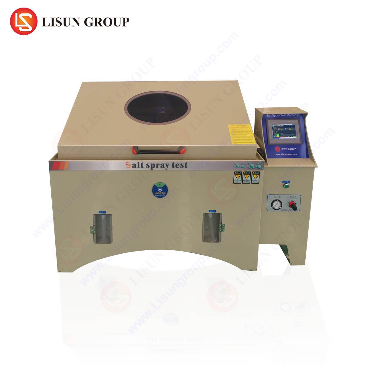
The LISUN Gauges for Plugs and Sockets System: A Case Study in Integrated Testing
The LISUN Gauges for Plugs and Sockets product line exemplifies the translation of these technical principles into a comprehensive laboratory solution. Designed for manufacturers and third-party certification bodies, the system provides a complete set of gauges for rigorous type testing and production line sampling.
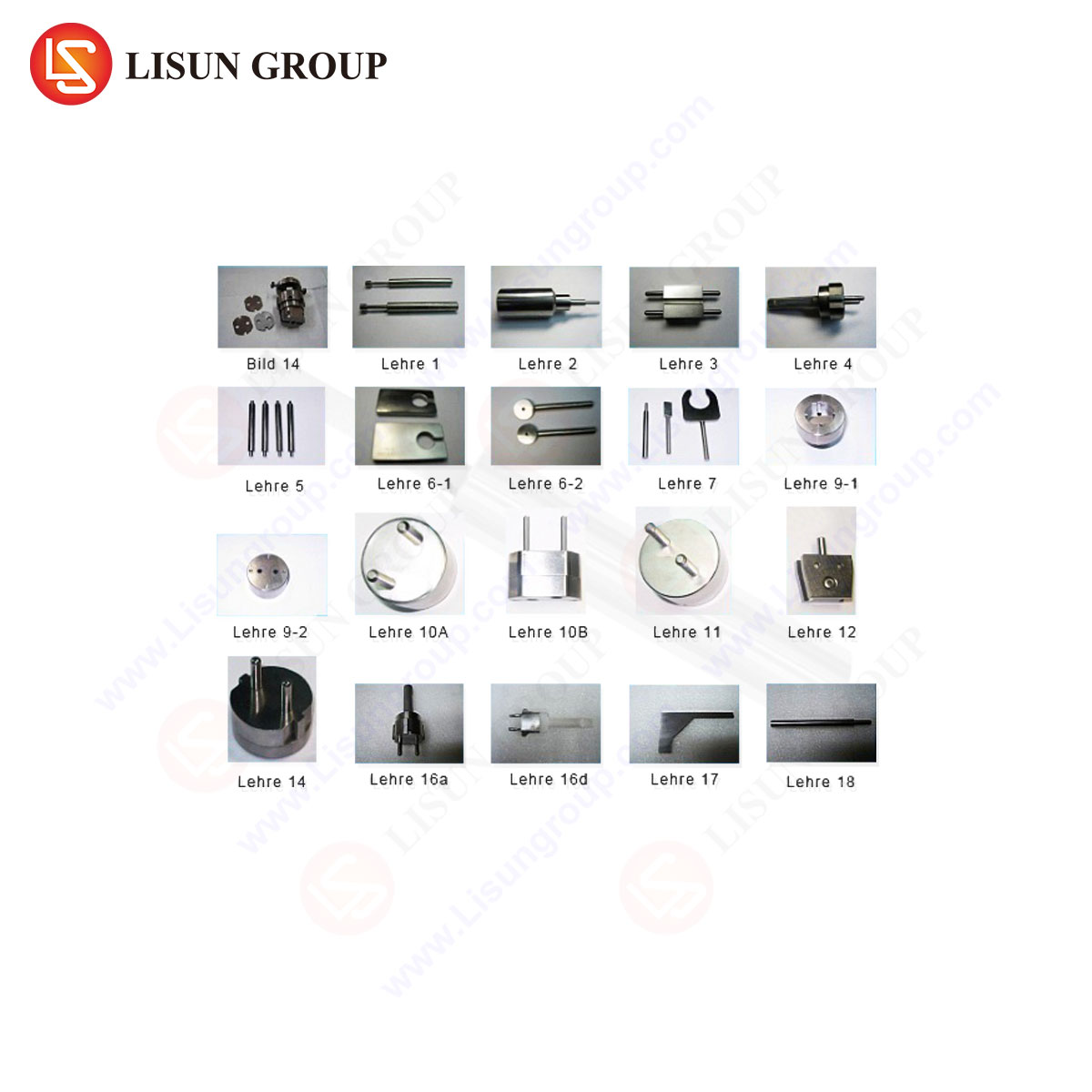
System Specifications and Configuration: A typical LISUN kit for 16A 250V AC systems includes a suite of precision-machined gauges. These are manufactured from hardened tool steel or other durable materials to resist wear and maintain dimensional stability over thousands of cycles. The set encompasses:
- Main “Go” Gauge: A full-form gauge representing the maximum allowable dimensions of a standard plug, used for the primary insertion test.
- “No-Go” or Prohibited Zone Gauges: These gauges, often of specific profiles or pin sizes, must not be able to enter the socket apertures or make contact with live parts, verifying safety barriers.
- Shutter Actuation Test Pins: Individual pin gauges used to test the independent and sequential operation of protective shutters in sockets designed with such features.
- Calibration Certification: Each gauge is supplied with documentation affirming its traceable calibration to international standards, a non-negotiable requirement for accredited laboratory work.
Testing Principles Embodied: The LISUN system operationalizes the clauses of standards like IEC 60884-1. For instance, it directly performs tests such as:
- Test 10 (Accessibility of Live Parts): Using the “no-go” gauges to ensure touch-protection.
- Test 12 (Operation of Shutters): Verifying that shutters open correctly only when the earth pin (or both line and neutral pins for non-earthed sockets) are inserted.
- Dimensional Compliance Checks: The core insertion test with the main gauge.
Industry Use Cases and Application Contexts: The primary application domains are:
- Product Development and Type Testing: Engineers use the gauge set during the design validation phase to ensure prototypes meet dimensional requirements before formal certification submission.
- Third-Party Certification Laboratories: Bodies like TÜV, Intertek, and UL employ such gauges as mandated equipment for evaluating products against safety standards.
- Incoming Quality Control (IQC) and Production Auditing: Manufacturers of socket-outlets use gauges for batch sampling to monitor production tooling wear and maintain consistent output quality.
- Standards Compliance Audits: Regulatory inspectors may utilize gauges for market surveillance, checking products already in the distribution chain.
Competitive Advantages in a Technical Context: The value of a system like LISUN’s is realized through several technical and operational merits:
- Material Integrity and Wear Resistance: The use of high-grade materials minimizes dimensional drift due to abrasion, ensuring long-term measurement reliability.
- Complete Standards Coverage: A fully comprehensive kit ensures a laboratory can perform all relevant gauge-based tests from a single, coherent source, reducing procurement complexity.
- Traceable Calibration: Integrated calibration services with documented traceability support ISO/IEC 17025 accreditation requirements for testing laboratories.
- Ergonomic and Durable Packaging: Organized, robust cases protect the precision instruments from damage and contamination, while facilitating efficient workflow in a laboratory setting.
Data Representation and Analysis of Gauge Testing
While the test outcome is fundamentally binary (pass/fail), quantitative data can be recorded for process control and analysis. A laboratory might log:
Table 1: Exemplary Test Data Log for 16A 250V Socket Dimensional Verification
| Socket Sample ID | Test: Main Gauge Insertion | Force Applied (N) | Observation/Result | Test: Shutter Operation | Result |
| :— | :— | :— | :— | :— | :— |
| SOCK-001 | Performed | 35 | Full insertion, face seated | Smooth, sequential opening | PASS |
| SOCK-002 | Performed | 40 | Binding at 3mm depth | Shutter hesitant, required excessive force | FAIL |
| SOCK-003 | Performed | 30 | Full insertion, face seated | Correct operation | PASS |
Statistical process control (SPC) charts could be applied to insertion force data over a production run, where a trending increase might indicate tooling wear in the socket molding process before it results in a non-conforming product.
Conclusion: The Critical Role of Precision in Passive Safety Verification
The 16A 250V AC plug gauge represents a quintessential example of a simple, passive tool delivering profound impact on product safety and interoperability. Its function, grounded in unambiguous mechanical interaction, provides a definitive check on the first layer of electrical safety: correct and secure physical connection. As plug and socket designs evolve—incorporating smart features, USB ports, or enhanced safety mechanisms—the fundamental requirement for dimensional conformity remains constant. Implementing a rigorous gauge testing regimen, supported by precision-engineered tools like the LISUN Gauges for Plugs and Sockets system, is an indispensable practice for any entity committed to manufacturing, certifying, or regulating safe and reliable electrical connection devices. It is through such meticulous verification that the foundational interface of electrical power delivery maintains its integrity across global markets.
FAQ Section
Q1: How often should a set of plug gauges be recalibrated?
A1: Recalibration intervals depend on usage frequency, material wear, and the laboratory’s own quality procedures under ISO/IEC 17025. A typical interval for active laboratory use is 12 months. However, if a gauge is dropped, shows visible damage, or its test results become questionable, immediate recalibration is necessary. Manufacturers like LISUN often provide recommended intervals and calibration services.
Q2: Can one gauge set be used for all 16A 250V socket types globally?
A2: No. The physical configuration of a 16A 250V plug varies significantly by region (e.g., British BS 1363, Australian AS/NZS 3112, European CEE 7/4, etc.). Each configuration requires a unique gauge set designed to the specific pin shape, spacing, and outline defined in the applicable national standard. A comprehensive laboratory will possess multiple gauge sets for the different socket types it evaluates.
Q3: What is the consequence of using a worn or out-of-calibration plug gauge?
A3: Using a non-conforming gauge compromises the entire testing process. A worn “go” gauge that is undersized may pass sockets that are too small, risking that genuine plugs will fit too tightly or not at all. An out-of-spec “no-go” gauge could fail safe sockets or, more dangerously, pass sockets that allow access to live parts. This can lead to non-compliant products reaching the market, with associated safety, liability, and recall risks.
Q4: Besides dimensional checks, what other tests are critical for full socket safety certification?
A4: Dimensional gauge testing is one part of a extensive test suite. Other critical evaluations include electrical endurance (plug insertion/withdrawal cycles), temperature rise under load, resistance to heat, aging, and moisture, mechanical strength (impact, crush resistance), insulation resistance, dielectric strength (hipot testing), and tests for terminal integrity and screw torque. Gauge testing is a vital first step in verifying the mechanical interface.
Q5: In a production environment, is 100% gauge testing of every socket outlet recommended?
A5: Typically, no. 100% testing for dimensions is often impractical and can induce wear on both the gauge and the product. Standard practice involves statistical quality control (SQC) using Acceptable Quality Level (AQL) sampling plans based on production batch size. However, all sockets should be visually inspected, and gauge testing is performed on a defined sample frequency. After tooling maintenance or changeover, increased sampling or 100% testing for a short run may be implemented.