


A Technical Analysis of the 16A Socket Shutter Force Test Gauge: Principles, Standards, and Implementation
Introduction to Shutter Safety Mechanisms in AC Power Sockets
The integral safety shutter mechanism within AC power sockets represents a critical engineering control designed to mitigate the risk of electric shock. These spring-loaded barriers, typically constructed from robust thermoplastics or composite materials, are engineered to obstruct access to the live and neutral contacts unless equalized pressure is applied simultaneously via the earth pin (in Type G, BS 1363 systems) or the live and neutral pins themselves (in Type F, Schuko systems). The functional efficacy of this safety feature is not binary; it is contingent upon a precise balance of mechanical forces. Excessive spring tension can render the socket unfit for purpose, causing user difficulty during insertion and potential damage to plug pins. Conversely, insufficient force compromises the fundamental safety objective, allowing for the inadvertent probing of energized contacts with foreign objects. Consequently, the quantitative measurement of the force required to actuate these shutters has emerged as a non-negotiable parameter in both manufacturing quality control and third-party compliance verification.
Defining the 16A Socket Shutter Force Test Parameter
The shutter force test is a quantifiable mechanical evaluation that measures the effort required to displace the protective shutters within a socket-outlet, thereby granting access to the underlying electrical contacts. For a 16-ampere socket, a common rating in domestic, commercial, and industrial applications globally, this parameter is rigorously defined by international and regional standards. The test does not merely assess the spring constant in isolation; it evaluates the entire mechanical system—including the geometry of the shutter levers, the pivot points, friction coefficients of interacting components, and the alignment of the test probe. The measured force, expressed in Newtons (N), must fall within a stipulated range. Exceeding the upper limit indicates a potential usability failure, while measuring below the lower threshold signals a definitive safety failure. This precise measurement is the exclusive domain of a specialized instrument: the 16A Socket Shutter Force Test Gauge.
Operational Principles of a Dedicated Shutter Force Test Gauge
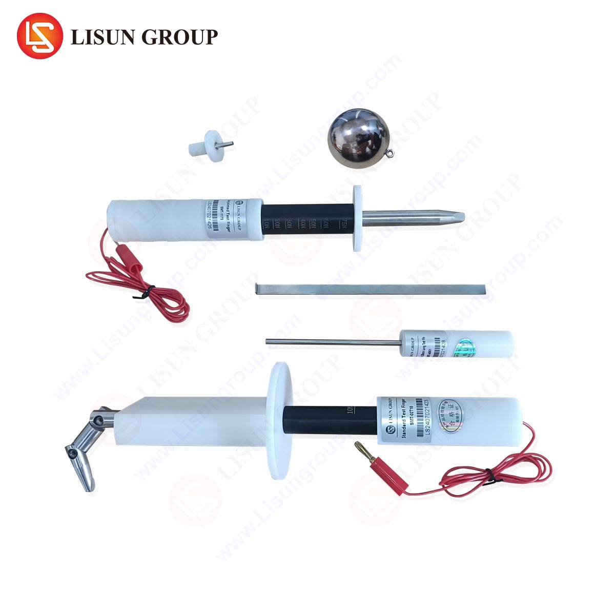
A dedicated test gauge transcends the functionality of a simple force meter. It is an integrated system comprising several key subsystems. The core is a precision load cell or force transducer, calibrated to traceable national standards, which converts mechanical force into an electrical signal. This sensor is interfaced with a probe assembly that precisely mimics the dimensional and geometric profile of a standard plug pin as specified by the relevant standard (e.g., the earth pin for BS 1363). The actuation mechanism is critical; it must apply force at a controlled, constant rate to ensure repeatable results, as the viscoelastic properties of plastics and the static friction of the mechanism can yield variable readings under different insertion speeds. Advanced gauges incorporate motorized drive systems to standardize this rate. The displacement of the probe is simultaneously measured, allowing for the generation of a force-displacement curve. This curve is diagnostically valuable, revealing not just the peak force (the primary compliance metric) but also the smoothness of operation, the presence of sticking points, or anomalous hysteresis, which can indicate suboptimal assembly or material defects.
LISUN Gauges for Plugs and Sockets: System Specifications and Architecture
The LISUN Gauges for Plugs and Sockets product line embodies a fully integrated approach to shutter force verification. Engineered for laboratory, production line, and audit environments, these systems are designed to deliver metrological rigor alongside operational efficiency. A representative model for 16A socket testing typically features a high-resolution digital force gauge with a sampling rate exceeding 500 Hz, ensuring no transient peak forces are missed. The gauge is mounted on a rigid, calibrated test stand with a vertically adjustable crosshead. The probe assembly is interchangeable, allowing the same base instrument to be configured for various socket types (e.g., Type G, Type F, Type I) by employing standard-compliant test pins.
Key specifications often include a measurement range of 0-50 N, with a resolution of 0.01 N and an accuracy of ±0.5% of full scale. The motorized drive provides a programmable test speed, commonly variable between 1-30 mm/min, aligning with the stipulations of standards like IEC 60884-1. The system is controlled via an intuitive HMI (Human-Machine Interface) or PC software, which not only records the peak force but also logs the complete test profile, stores results against product batch IDs, and provides clear PASS/FAIL indications against user-defined limits. Data export functionality for statistical process control (SPC) analysis is a standard feature, enabling trend monitoring and proactive manufacturing adjustments.
Relevant International Standards and Compliance Frameworks
The design and application of shutter force test gauges are inextricably linked to a framework of international safety standards. These documents provide the definitive test methodologies, probe dimensions, and force limits. The paramount standard is IEC 60884-1, “Plugs and socket-outlets for household and similar purposes – Part 1: General requirements.” This standard is adopted or harmonized nationally, giving rise to BS 1363 (UK), AS/NZS 3112 (Australia/New Zealand), and similar derivatives. For 16A sockets, Clause 13.22 of IEC 60884-1 (and its national equivalents) explicitly details the shutter force test procedure. It specifies the exact dimensions of the test pin, the angle of approach, the speed of insertion, and the permissible force limits. For example, BS 1363 mandates that the force required to open the shutters using the specified test pin shall not exceed 40 N. Other regional standards, such as those for Schuko (Type F) sockets, have analogous but distinct requirements, often involving simultaneous actuation by two probes. A compliant test gauge must, therefore, be configurable to adhere to the precise geometric and procedural dictates of each target standard.
Integration into Manufacturing Quality Assurance Protocols
Within a high-volume socket manufacturing environment, the shutter force test gauge transitions from a periodic verification tool to a critical in-process control node. Its integration can occur at multiple stages. Incoming quality inspection (IQC) utilizes the gauge to validate shutter mechanisms from subcontractors or internal molding departments. During sub-assembly, it can test the shutter module prior to its installation into the socket housing. Most critically, it is employed in 100% final testing or via automated sampling plans on the finished product line. Automated test stations, often built around the core LISUN gauge mechanism, can test multiple outlets on a multi-gang socket assembly in sequence, dramatically increasing throughput. The instantaneous feedback provided—such as a visual or auditory alarm for a unit falling outside tolerance—allows for immediate corrective action, preventing the accumulation of non-conforming product. The historical data collected supports root cause analysis, whether the issue stems from spring fatigue, molding flash impeding movement, or dimensional drift in component parts.
Diagnostic Interpretation of Force-Displacement Data
The numerical value of peak shutter force, while the primary compliance metric, is merely the apex of a rich dataset. A sophisticated gauge captures the entire force profile throughout the probe’s travel. Analyzing this profile offers profound diagnostic insights. An ideal profile shows a smooth, monotonic increase in force to a well-defined peak, followed by a sharp drop as the shutter passes over its detent (the “break-over” point). Deviations from this ideal are indicative of specific manufacturing flaws:
- High Initial Friction Spike: A sharp peak at the very beginning of travel suggests misalignment, burrs on the shutter or pin entry, or excessive molding flash.
- Multiple Peaks or Oscillations: This “sticky” profile typically indicates high friction at pivot points, insufficient lubrication, or uneven surface finishes on interacting plastic parts.
- Excessively Broad or Rounded Peak: A gradual force increase may point to a spring that is nearing the end of its specified tolerance or a geometric design where the mechanical advantage changes sub-optimally during actuation.
- High Hysteresis (Difference between insertion and retraction force): Significant differences between the force curves during insertion and withdrawal can reveal plastic deformation or excessive wear in the mechanism.
This analytical capability transforms the test gauge from a simple go/no-go device into a powerful tool for engineering and process refinement.
Comparative Advantages of Dedicated System Architecture
The use of a dedicated, integrated gauge system like those offered by LISUN presents distinct advantages over ad-hoc solutions employing generic push-pull force gauges. First is metrological integrity: The system is designed and calibrated as a whole, ensuring the alignment of the probe, the direction of force application, and the measurement axis are perfectly coaxial, eliminating cosine errors. Second is procedural fidelity: Programmable, motorized actuation guarantees a consistent test speed, a variable that manual testing cannot control, directly impacting result repeatability. Third is ergonomic efficiency: Automated testing reduces operator fatigue and variability, while the integrated software handles data logging, eliminating manual transcription errors. Finally, there is future-proofing: A modular system can be updated with new probe sets and software to accommodate evolving standards or new product lines, protecting the capital investment.
Case Study: Application in Third-Party Certification Laboratories
Independent testing and certification bodies (e.g., those providing marks like BSI Kitemark, ASTA, Intertek’s ETL mark) represent a paramount use case where measurement uncertainty must be minimized. In this setting, the LISUN gauge serves as a reference instrument. Its traceable calibration certificate is a mandatory document for laboratory accreditation under ISO/IEC 17025. During type-testing for certification, the shutter force test is performed as a destructive test on multiple samples from a production batch. The gauge’s ability to produce detailed, auditable test reports with full traceability (including timestamp, operator, calibration status, and raw data) is not merely beneficial but a contractual and regulatory requirement. The objective data it provides forms a non-negotiable part of the technical file assessing a product’s conformity to essential safety requirements.
Maintenance, Calibration, and Ensuring Long-Term Metrological Traceability
To maintain the validity of test results, a rigorous regime of preventive maintenance and periodic calibration is essential. The mechanical components, particularly the probe tip and drive mechanism, must be inspected regularly for wear or damage. Calibration, performed at intervals recommended by the manufacturer or dictated by quality procedures (typically annually), involves comparing the gauge’s output against a reference standard force measurement device in a accredited calibration laboratory. This process verifies the instrument’s accuracy across its entire range and ensures its measurement uncertainty remains within acceptable bounds. For systems like the LISUN gauge, this often involves a two-tier process: calibrating the digital force indicator separately and then performing a system verification using a standard test jig to confirm the integrated performance of the probe, drive, and sensor.
Conclusion: The Role of Precision Measurement in Electrical Safety
The 16A socket shutter, a seemingly simple plastic component, is a vital guardian against electric shock hazards. Its performance is quantifiable, and that quantification demands precision instrumentation. The dedicated shutter force test gauge, as exemplified by integrated systems from manufacturers like LISUN, provides the necessary nexus between safety intent and verified performance. By enabling precise, repeatable, and standards-compliant measurement, it supports manufacturers in building safer products, empowers certifiers to validate compliance objectively, and ultimately contributes to the reduction of electrical accidents in households and workplaces worldwide. Its role is a testament to the principle that effective safety engineering relies not only on good design but also on rigorous, quantitative verification.
Frequently Asked Questions (FAQ)
Q1: Can a single LISUN gauge test different types of sockets (e.g., UK 13A and EU 16A Schuko)?
A: Yes, provided the system is of a modular design. The core force measurement unit and drive mechanism are standard. Testing different socket types requires changing the probe assembly to the specific test pins mandated by the respective standard (e.g., BS 1363 earth pin for UK sockets, and the dual-pin probe assembly for Schuko shutters). The software limits can also be reconfigured for the different force requirements of each standard.
Q2: How often should the test gauge be calibrated, and what does the process entail?
A: Calibration frequency is typically annual for most quality and certification environments, though more frequent intervals may be dictated by high usage or specific accreditation requirements. The process involves sending the digital force gauge module to an accredited metrology lab for comparison against master standards. A full system verification should also be performed on-site using a calibrated weight set or a transfer standard to confirm the complete test stand’s performance, including alignment and drive mechanism.
Q3: What is the most common cause of shutter force test failure during production?
A: The most prevalent cause is variation in the spring force, often due to spring tolerances, heat treatment inconsistencies, or fatigue. The second most common cause is dimensional interference from molding flash or slight misalignment of the shutter module within the socket housing, leading to increased friction. The force-displacement curve from the gauge is key to diagnosing which root cause is responsible.
Q4: Is the shutter force test a pass/fail test, or can the data be used for process improvement?
A: While compliance is determined by a pass/fail threshold, the data is immensely valuable for process improvement. Statistical analysis of force results over time can reveal trends, such as a gradual increase in average force, signaling potential tool wear in the molding press or a change in spring supplier quality. This enables proactive maintenance and prevents batches from falling out of specification.
Q5: Does the standard specify an environmental condition for testing, such as temperature or humidity?
A: IEC 60884-1 and related standards typically require that type-tests be conducted under a “normalized” laboratory environment, generally within a range of 15-35°C and a relative humidity conducive to stable measurements. While not always explicitly mandated for the shutter test alone, conducting tests in a stable environment is considered good practice, as extreme temperatures can affect the mechanical properties of plastic components and springs, potentially skewing results.