


Methodologies and Applications of Accelerated Weathering Testing in Modern Industry
Introduction to Accelerated Weathering Simulation
The long-term reliability and safety of materials and components are non-negotiable prerequisites across virtually all manufacturing sectors. In-service failures attributable to environmental degradation—whether from thermal cycling, humidity ingress, UV radiation, or corrosive atmospheres—result in significant financial loss, compromised safety, and reputational damage. Natural weathering studies, while accurate, are prohibitively time-consuming, often requiring years of exposure to gather meaningful data. This temporal impracticality has cemented the role of accelerated weathering testers as indispensable tools in the product development and qualification lifecycle. These instruments artificially replicate and intensify environmental stresses, enabling engineers to predict years of field performance within weeks or months of laboratory testing. The resultant data informs material selection, design improvements, and compliance with international standards, thereby de-risking product launches and ensuring operational longevity.
Fundamental Principles of Environmental Stress Acceleration
Accelerated weathering testing operates on the foundational principle of time-compression through the controlled application of exaggerated environmental parameters. This is not merely a process of “speeding up” time, but a sophisticated simulation that isolates and intensifies specific stress factors known to induce failure modes observed in real-world conditions. The core mechanisms include photodegradation from intensified ultraviolet (UV) light spectra, thermal oxidation from elevated temperatures, hydrolysis from condensed or high-humidity environments, and mechanical stress from thermal expansion and contraction cycles. Crucially, effective acceleration requires a scientifically validated correlation between laboratory-induced failures and field performance. This correlation is established through meticulous calibration of test parameters—light irradiance, chamber temperature, black panel temperature, and humidity levels—against known climatic data and failure analytics. Standards organizations such as ASTM International, the International Electrotechnical Commission (IEC), and the International Organization for Standardization (ISO) provide rigorous protocols (e.g., ASTM G154, IEC 60068-2-30, ISO 4892) to ensure tests are repeatable, reproducible, and meaningful.
The Critical Role of Thermal Shock Testing in Electronics Reliability
Among the various accelerated weathering techniques, thermal shock testing represents one of the most severe and revealing evaluations for assembled products and components. This test subjects a specimen to rapid, extreme transitions between high and low temperature extremes. The resultant physical stresses are profound: different materials within a single assembly (e.g., semiconductors, solder joints, ceramics, plastics, and metals) possess distinct coefficients of thermal expansion (CTE). During a rapid temperature transition, these materials expand and contract at different rates, generating shear forces at their interfaces. This can induce latent defects, precipitate crack propagation in substrates and conformal coatings, break electrical connections, and delaminate layered structures. For modern, miniaturized electronics, these failures are critical. Thermal shock testing, therefore, is not a test of temperature endurance per se, but a test of structural and interfacial integrity under the mechanical strain induced by thermal transience.
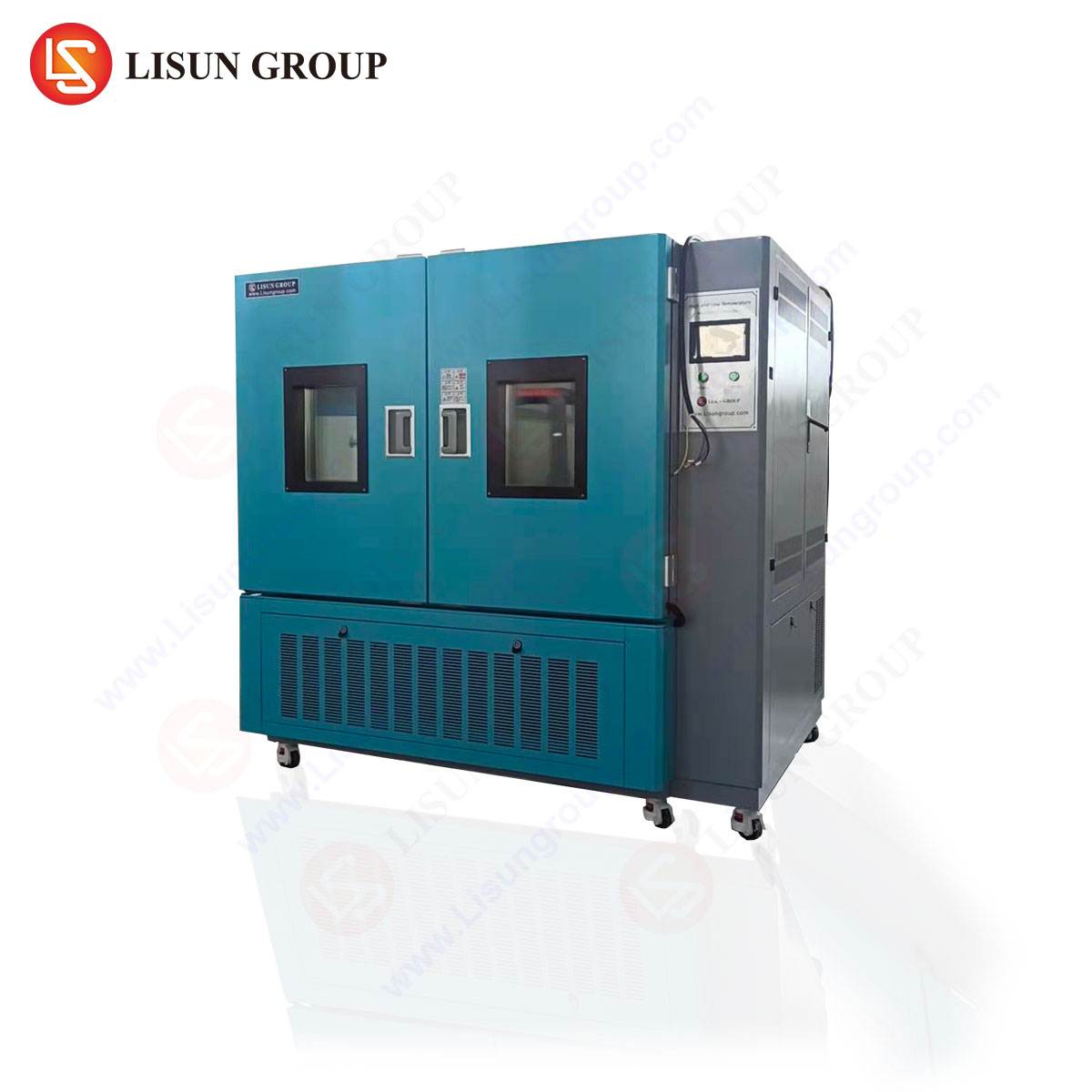
HLST-500D Thermal Shock Test Chamber: Architecture and Operational Protocol
The LISUN HLST-500D Thermal Shock Test Chamber is engineered to deliver precise and reliable two-zone thermal shock testing in compliance with major international standards, including IEC 60068-2-14 (Test N: Change of temperature). Its design facilitates a rigorous assessment of product robustness through a defined operational protocol.
The chamber comprises three key sections: a high-temperature zone, a low-temperature zone, and a movable basket that transfers test specimens between them. The transfer mechanism is a critical component, designed to minimize transition time—a key parameter in shock testing. The HLST-500D achieves a transfer time of less than 10 seconds, ensuring the specimen experiences the full severity of the temperature differential as a true shock rather than a gradual ramp.
Testing Principle: A test cycle begins with the specimen basket stationed in either the high- or low-temperature zone for a user-defined dwell time, ensuring the specimen’s internal temperature stabilizes at the extreme. The basket then rapidly transfers the specimen to the opposite zone, where it again dwells until stabilized. This constitutes one cycle. The test continues for hundreds or thousands of cycles, depending on the specification requirement.
Key Specifications of the HLST-500D:
- Temperature Range: High Temperature Zone: +60°C to +150°C; Low Temperature Zone: -10°C to -55°C (or -65°C optional).
- Temperature Fluctuation: ±0.5°C.
- Temperature Deviation: ±2.0°C.
- Recovery Time: ≤5 minutes (from +150°C to -55°C or vice versa upon door closing).
- Transfer Time: <10 seconds.
- Basket Load Capacity: 15kg.
- Internal Dimensions: 500 x 500 x 400 mm (W x D x H).
The chamber utilizes a balanced heating system and a cascade refrigeration system to achieve rapid temperature recovery, ensuring consistent test conditions throughout protracted testing schedules.
Industry-Specific Applications of Thermal Shock Testing
The application of the HLST-500D spans industries where electronic and electromechanical systems must survive harsh environmental transitions.
Automotive Electronics: Modern vehicles contain over a hundred electronic control units (ECUs). An engine control module may experience ambient temperatures exceeding 85°C under the hood, while during a cold start in winter, it could be at -30°C. Thermal shock testing validates the integrity of solder joints on printed circuit boards (PCBs), the bonding of power semiconductor packages, and the sealing of connectors against this reality.
Aerospace and Aviation Components: Avionics systems undergo extreme temperature swings from ground operations in desert heat to cruising altitudes with ambient temperatures below -50°C. The HLST-500D is used to qualify components like flight data recorders, navigation system modules, and communication equipment, ensuring no failure occurs due to CTE mismatch in materials after repeated ascent and descent cycles.
Telecommunications Equipment: 5G base station amplifiers and outdoor optical network units (ONUs) are exposed to diurnal and seasonal temperature variations. Thermal shock testing accelerates the aging of these units, identifying potential failures in fiber optic splices, antenna array connections, and outdoor enclosure seals before they are deployed in the field.
Medical Devices: Implantable devices like pacemakers and neurostimulators must maintain absolute reliability after sterilization processes and inside the human body. Portable diagnostic equipment used in ambulances or field hospitals faces wide temperature ranges. Thermal shock testing assures the hermeticity of sealed implants and the functional stability of critical portable devices.
Lighting Fixtures: High-power LED luminaires for street lighting or industrial use generate significant heat during operation but are installed in outdoor environments. The rapid thermal cycling between the self-heated state and cold ambient rain can cause lens cracking or LED detachment. Testing with the HLST-500D helps manufacturers design robust thermal management and mechanical attachment systems.
Electrical Components and Wiring Systems: Circuit breakers, switches, and terminal blocks experience current-induced heating followed by cooling. This cyclic stress can loosen connections or degrade insulating materials. Similarly, cable assemblies and connectors are tested to ensure crimps, insulations, and potting compounds do not fail when subjected to rapid temperature changes, which could lead to short circuits or signal loss.
Correlation of Accelerated Testing to Real-World Service Life
A central challenge in accelerated weathering is establishing a quantifiable correlation between test cycles and actual years of service. This is not a universal multiplier but a derived relationship based on failure mechanism analysis. For thermal shock, the correlation often hinges on the induced strain energy per cycle. By knowing the material properties (CTE, modulus of elasticity) and the temperature delta (ΔT), engineers can calculate the approximate strain. Field data on failure rates under known thermal cycling conditions (e.g., daily and seasonal cycles in a specific geographic location) are then used to anchor the laboratory test.
For example, a specification might require 500 cycles between -40°C and +125°C. This could be correlated to representing 10 years of service for an under-hood automotive component based on historical failure data models. The validation often involves complementary tests, such as vibration during temperature cycling or power cycling within the thermal shock chamber, to better simulate concurrent real-world stresses.
Standards Compliance and Testing Regimens
The HLST-500D facilitates compliance with a suite of critical standards, which define not only the equipment performance but the test procedures. Key referenced standards include:
- IEC 60068-2-14 Test N: The foundational standard for change of temperature tests, detailing procedures for rapid change (thermal shock).
- MIL-STD-202G, Method 107G: A U.S. military standard for thermal shock testing of electronic components.
- JESD22-A104: The JEDEC standard for temperature cycling, often referenced for semiconductor devices.
- ISO 16750-4: An automotive standard for environmental testing, which includes thermal shock requirements for electrical and electronic equipment.
A typical test regimen defined by such a standard will specify the extreme temperatures, the dwell time at each extreme (e.g., 30 minutes or until thermal stabilization), the transfer time (which the HLST-500D ensures is <10 sec), and the total number of cycles. Functional and parametric testing of the unit under test is performed at intervals during the test to monitor degradation.
Comparative Advantages in Precision and Control
The efficacy of an accelerated weathering tester is measured by its precision, repeatability, and control fidelity. The HLST-500D incorporates several design features that confer competitive advantages in these areas. The use of a cascade refrigeration system allows it to reach and maintain deep sub-zero temperatures with rapid recovery, a capability not all single-stage systems possess. The precision in temperature fluctuation (±0.5°C) and deviation (±2.0°C) ensures that the stress applied is consistent across the test volume and from one test to the next, which is paramount for generating reliable, comparable data. The robust basket transfer system, with a load capacity of 15kg, is engineered for minimal maintenance and consistent sub-10-second transfer over thousands of cycles, a critical factor in maintaining test severity. Furthermore, the chamber’s construction with high-quality insulation and sealed dampers minimizes thermal leakage and cross-talk between zones, preserving the integrity of each extreme environment.
Integrating Accelerated Testing into the Product Development Lifecycle
The strategic implementation of accelerated weathering testing, such as that performed by the HLST-500D, is most effective when integrated early and throughout the product development lifecycle. During the design phase, it is used for design verification testing (DVT) to compare material and assembly choices. In the prototyping phase, it identifies latent manufacturing defects or design flaws before tooling is finalized. For production qualification, it serves as a gatekeeper, ensuring each manufacturing lot meets durability specifications. Finally, in ongoing reliability testing (ORT), it provides continuous monitoring of production quality. This integrated approach transforms testing from a final compliance hurdle into a proactive engineering tool, driving improvements in design robustness, manufacturing process control, and ultimately, product field reliability across the demanding sectors of electronics, automotive, aerospace, and telecommunications.
FAQ: Thermal Shock Testing with the HLST-500D
Q1: What is the primary difference between thermal shock testing and temperature cycling?
A1: The key distinction is the rate of temperature change. Thermal shock testing, as performed by the HLST-500D, involves an extremely rapid transfer (typically <30 seconds) between two extreme temperature zones, creating a severe mechanical stress. Temperature cycling generally involves a slower, controlled ramp rate between extremes, placing more emphasis on steady-state dwell times and often targeting different failure mechanisms like intermetallic growth.
Q2: How do you determine the appropriate high and low temperature set points for testing our automotive electronic control unit (ECU)?
A2: The set points are typically derived from the product specification sheet, which should define its operational and storage temperature ranges. They are often expanded beyond these limits for safety margin. Furthermore, specific automotive OEM standards (like ISO 16750 or company-specific specifications) usually prescribe exact test conditions. For an under-hood ECU, a common test profile might be -40°C to +125°C, based on the most severe expected environmental exposure.
Q3: Can the HLST-500D accommodate testing with powered devices (power cycling during the test)?
A3: While the HLST-500D chamber itself provides the environmental stress, it is standard practice to integrate external monitoring and power cycling equipment. Test specimens are wired through sealed ports in the chamber wall. The chamber’s programmable controller can often be synchronized with external test sequencers to turn power on/off or perform functional tests at specific points in the thermal cycle, providing a more comprehensive simulation of operational stress.
Q4: What is the significance of the “transfer time” specification, and why is less than 10 seconds important?
A4: Transfer time is the duration the specimen takes to move from the ambient of one extreme zone to the ambient of the other. A longer transfer time allows the specimen to partially equilibrate during transit, reducing the effective thermal shock and the resultant mechanical strain. A sub-10-second transfer, as achieved by the HLST-500D, ensures the specimen’s surface and internal components experience the full, abrupt temperature change, making the test more severe and accelerating the revelation of CTE-mismatch failures.
Q5: How often does the chamber require calibration and maintenance to ensure test validity?
A5: Calibration of temperature sensors should be performed at least annually, traceable to a national standard, as required by quality systems like ISO/IEC 17025. Preventive maintenance includes regular inspection of the basket transfer mechanism, cleaning of air filters, checking refrigerant levels, and verifying the sealing of chamber doors and dampers. Adherence to the manufacturer’s recommended maintenance schedule is crucial for ensuring long-term performance and the reproducibility of test results.