


Advanced Environmental Testing Solutions: Ensuring Reliability in Modern Electronic and Electromechanical Systems
The relentless progression of technological miniaturization, functional integration, and global market deployment has irrevocably elevated the criticality of environmental reliability testing. For manufacturers across a spectrum of industries—from automotive electronics to medical devices—the operational lifespan and failure-free performance of components and finished products are non-negotiable parameters dictated by both market expectations and stringent regulatory frameworks. Advanced environmental testing solutions, therefore, transcend mere quality control checkpoints; they constitute a fundamental engineering discipline that simulates years of operational stress within a controlled laboratory timeframe. This technical discourse examines the methodologies, applications, and technological implementations underpinning these solutions, with a particular focus on the pivotal role of precision climatic and thermal shock testing.
The Imperative of Accelerated Lifecycle Simulation
In-situ field failure of a product is economically catastrophic and, in sectors like aerospace or medical devices, potentially hazardous. The core objective of advanced environmental testing is to precipitate latent defects and material weaknesses prior to market release through accelerated stress conditioning. This process is governed by the Arrhenius equation and related models, which establish a quantifiable relationship between elevated stress levels—such as temperature, humidity, and thermal cycling—and the acceleration of failure mechanisms. By exposing a unit under test (UUT) to conditions that exceed typical operational envelopes, engineers can identify failure modes related to coefficient of thermal expansion (CTE) mismatches, corrosion, intermetallic growth, polymer embrittlement, and condensation-induced leakage currents. The data derived are not merely pass/fail metrics but are integral to failure analysis, design iteration, and the validation of mean time between failures (MTBF) predictions.
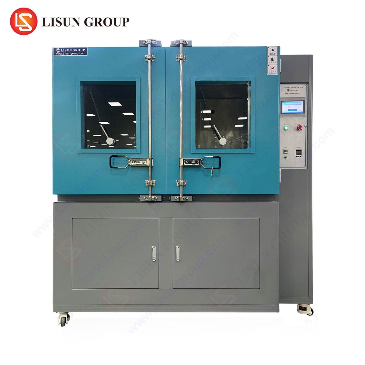
Climatic Stress Testing: Principles and Technological Execution
Climatic testing, encompassing controlled temperature and humidity conditioning, remains a cornerstone of environmental reliability assessment. The test chamber facilitating this must provide not only a broad range of conditions but also exceptional uniformity, stability, and rate-of-change fidelity to ensure reproducible, standardized results. The testing principle involves placing the UUT within a thermally insulated workspace where air is continuously circulated over heating elements, refrigeration coils, and a humidity generation system—typically a steam generator or ultrasonic atomizer for precise control.
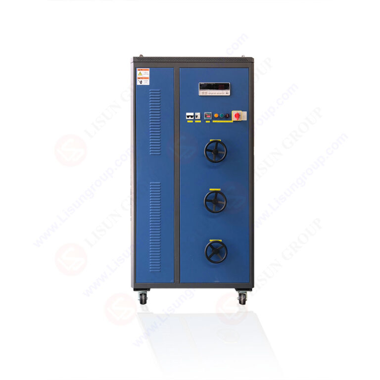
A representative instrument in this category is the LISUN GDJS-015B Temperature Humidity Test Chamber. This chamber is engineered to deliver a comprehensive climatic stress profile with technical specifications that meet or exceed common industry standards such as IEC 60068-2-1 (cold), IEC 60068-2-2 (dry heat), and IEC 60068-2-78 (damp heat). Its operational envelope spans a temperature range of -70°C to +150°C, with a humidity range of 20% to 98% RH. Critical to its performance is the rate of temperature change, which can achieve approximately 3°C/min under linear programming, enabling simulation of rapid diurnal cycles. The chamber utilizes a cascade refrigeration system to attain its lower temperature extremes, ensuring stable performance at sub-zero conditions, while a dedicated dehumidification system allows for precise low-humidity setpoints—a requirement often overlooked yet essential for testing products destined for arid geographical regions.
The competitive advantage of such a system lies in its control precision and spatial uniformity. Specifications often cite a temperature uniformity of ≤±2.0°C and a humidity deviation of ≤±2.5% RH (≥75% RH) within the workspace. This level of control is paramount when testing sensitive electronic assemblies where localized condensation or thermal gradients could yield misleading results. For instance, validating a telecommunications base station power supply for deployment in Southeast Asia requires sustained exposure to 85°C/85% RH (a common damp heat test) for thousands of hours. Any fluctuation in chamber conditions could inaccurately accelerate or decelerate corrosion processes, compromising the validity of the test.
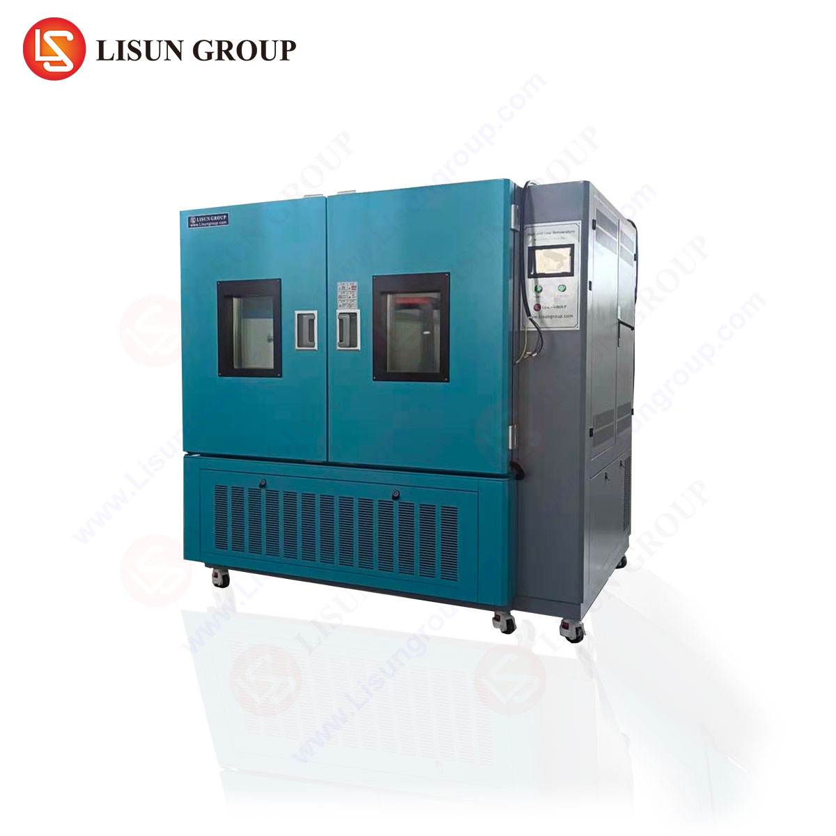
Thermal Shock Testing: Inducing Mechanical Stress Through Rapid Transition
While climatic testing applies steady-state or slowly cycling stresses, thermal shock testing is designed to induce severe mechanical stresses through rapid transitions between extreme temperatures. This test is particularly effective at revealing flaws in assemblies comprising materials with dissimilar CTEs, such as surface-mount technology (SMT) solder joints, bonded components, and encapsulated modules. The fundamental principle involves subjecting the UUT to alternating exposures in two (or three) independent temperature zones—a high-temperature zone and a low-temperature zone—with transfer mechanisms that minimize transition time.
The LISUN HLST-500D Thermal Shock Test Chamber exemplifies a two-zone (basket transfer) system engineered for this rigorous duty cycle. Its specification defines a high-temperature chamber range up to +200°C and a low-temperature chamber range down to -75°C. The defining performance metric for any thermal shock chamber is the recovery time and transfer time. The HLST-500D is designed to achieve a transfer time of ≤10 seconds, ensuring the UUT experiences the full thermal differential almost instantaneously. Following the transfer, the chamber must rapidly recover to its target setpoint; this model typically recovers within 5 minutes after loading. This rapid cycling, often conducted for hundreds of cycles, accelerates fatigue failure mechanisms that might take years to manifest under normal use.
The engineering of such a chamber involves significant challenges. The basket transfer mechanism must be exceptionally robust and reliable, as it executes thousands of movements during a single test regimen. Insulation between the two extreme zones must be highly efficient to prevent thermal cross-talk. Furthermore, the air circulation within each zone must be vigorous and uniform to ensure the UUT’s entire mass experiences the temperature change simultaneously, preventing thermal lag that could produce non-uniform stresses.
Industry-Specific Applications and Standards Compliance
The application of these testing methodologies is dictated by the unique failure modes and operational environments of each industry sector.
-
Automotive Electronics & Aerospace Components: These sectors demand perhaps the most rigorous testing profiles. Electronic control units (ECUs), sensors, and lighting fixtures are tested per standards like ISO 16750-4 (climate) and AEC-Q100. The GDJS-015B can simulate under-hood temperatures exceeding 125°C coupled with humidity, while the HLST-500D replicates the shock of a component powering up in a frozen state after an Arctic night or the repeated heating from a lamp housing and cooling from high-altitude flight or rain splash.
-
Medical Devices & Telecommunications Equipment: Reliability is directly linked to safety and continuous service. Implantable device components, diagnostic equipment, and 5G infrastructure hardware are tested to standards such as IEC 60601-1 and Telcordia GR-63. Long-term damp heat testing in the GDJS-015B assesses hermetic seal integrity and biocompatibility, while thermal shock in the HLST-500D validates the robustness of solder joints in RF amplifiers and fiber-optic transceivers against field temperature fluctuations.
-
Consumer Electronics, Appliances, & Industrial Controls: For products like smartphones, IoT devices, industrial PLCs, and household appliances, testing ensures consumer satisfaction and longevity. Tests often combine cyclic humidity with temperature variations to assess printed circuit board assembly (PCBA) corrosion resistance, display performance, and plastic housing durability. Rapid thermal shock is used to test the reliability of ball grid array (BGA) packages and connector interfaces.
-
Electrical Components & Wiring Systems: Switches, sockets, circuit breakers, and cable assemblies are tested for performance under extreme conditions. A cable connector, for instance, may undergo thermal shock testing to ensure the insulating materials do not crack and that metallic contacts maintain proper spring tension, preventing increased contact resistance—a potential fire hazard.
Integration into the Product Development and Validation Workflow
Advanced environmental testing is not an isolated activity but is integrated into a product’s lifecycle from design verification (DVT) to production validation (PVT) and qualification testing. During DVT, chambers like the GDJS-015B are used for margin testing, pushing designs beyond specification limits to identify weak points. In PVT, statistically significant sample sizes are subjected to standardized qualification tests to ensure manufacturing process robustness. The data acquisition systems integral to these chambers, which log temperature, humidity, and cycle counts, provide the objective evidence required for compliance reports and certification dossiers for bodies like UL, TÜV, or the FDA.
The selection of a testing instrument, therefore, hinges on several factors beyond basic range specifications: measurement accuracy and uniformity, reliability under continuous duty cycles, programmability for complex multi-segment profiles, and the ability to interface with external monitoring equipment to record the UUT’s performance in-situ during the test.
Conclusion: The Correlation Between Test Rigor and Field Reliability
The sophistication of modern environmental testing solutions directly mirrors the complexity and reliability expectations of today’s engineered products. Instruments such as the LISUN GDJS-015B and HLST-500D provide the controlled, repeatable, and severe conditions necessary to precipitate failure mechanisms in a predictive manner. By implementing a rigorous regimen of climatic and thermal shock testing, manufacturers across the electrical, electronic, and electromechanical sectors can mitigate field failure risks, reduce warranty costs, accelerate time-to-market for robust designs, and ultimately fulfill their obligations for safety and reliability. In an era where product integrity is paramount, these advanced testing solutions form the indispensable bridge between theoretical design and proven field performance.
FAQ Section
Q1: What is the fundamental difference between temperature cycling and thermal shock testing?
Temperature cycling typically involves a single chamber where the temperature is ramped at a controlled rate (e.g., 3°C/min to 15°C/min) between setpoints. This induces stress but allows some time for material equilibration. Thermal shock testing utilizes two or more chambers at fixed, extreme temperatures, with the test specimen mechanically transferred between them in seconds. This maximizes the thermal gradient across the specimen at the moment of transfer, inducing more severe mechanical shear stresses, and is specifically designed to test for interconnect and material interface failures.
Q2: When validating a medical device, why is humidity control precision at high temperatures so critical?
Many medical device qualification standards, such as those derived from IEC 60601-1, specify damp heat tests (e.g., 40°C/93% RH for 21 days). Precise control is critical because humidity, particularly at elevated temperatures, drives failure mechanisms like electrochemical migration, hydrolytic degradation of polymers, and corrosion of metallic traces. A deviation of ±5% RH at this setpoint could significantly alter the rate of moisture absorption and subsequent chemical reactions, leading to non-comparable test results and potentially allowing a marginal design to pass.
Q3: For automotive electronics testing, can a two-zone thermal shock chamber like the HLST-500D replicate the full temperature range required by some standards?
While the HLST-500D’s range of -75°C to +200°C covers the vast majority of automotive test profiles, some specific standards, particularly those for under-hood components or sensors in extreme locations, may call for a cold soak as low as -85°C or a high temperature exceeding +200°C. It is essential to cross-reference the chamber specifications with the exact requirements of the applicable test standard (e.g., ISO 16750, OEM-specific specs) before test initiation. Three-zone chambers or separate extreme-range chambers may be necessary for those specific use cases.
Q4: How does the rate of temperature change in a climate chamber affect the test outcome for a complex assembly?
A slower rate of change allows more time for thermal equilibration across the entire assembly. Different materials and components with varying mass and thermal conductivity will experience smaller transient differentials. A faster ramp rate, conversely, creates larger instantaneous temperature differences within the assembly. This can more effectively stress bonded interfaces, solder joints, and encapsulated components by exacerbating CTE mismatch effects. The chosen ramp rate should reflect the most severe real-world operational or storage scenarios the product is likely to encounter.