


Advancements in Fire Hazard Assessment: Methodologies, Standards, and Instrumentation for Modern Materials and Components
The proliferation of complex polymers, composite materials, and densely packed electronic assemblies across diverse industries has necessitated a concomitant evolution in fire hazard testing methodologies. Traditional pass/fail tests, while foundational, often provide insufficient data for predicting real-world fire behavior under fault conditions. Contemporary engineering demands a more nuanced, physics-based approach to flammability assessment, one that quantifies ignition propensity, flame spread kinetics, and the potential for fire propagation from small internal sources. This article delineates advanced fire hazard testing paradigms, focusing on the simulation of low-energy ignition sources and the critical standards governing these evaluations. Emphasis is placed on the needle flame test, a pivotal method for assessing the fire hazard presented by compact components and sub-assemblies.
The Imperative for Simulating Fault-Condition Ignition Sources
A significant proportion of fires in electrical and electronic equipment originate not from large external flames, but from small, internal thermal faults. These can include overheating connections, failed components, overloaded circuits, or arcing within switches and sockets. Conventional horizontal or vertical flame tests, which apply a substantial Bunsen burner flame to a specimen’s edge, may not accurately replicate the thermal insult of such localized, low-energy events. Consequently, a component might pass a general flammability test yet remain vulnerable to ignition under specific fault conditions, posing a latent hazard.
Advanced testing addresses this gap by employing ignition sources that better mimic these realistic scenarios. The technical objective shifts from merely determining if a material burns to understanding how it responds to a small flame applied directly to a vulnerable point, such as a seam, a thin wall, or an area adjacent to a heat-generating element. This philosophy underpins standards like IEC 60695-11-5, which defines the needle flame test. The method is predicated on the principle that by subjecting a specimen to a controlled, small flame (typically with a nominal power output of 1W), one can evaluate its ability to resist ignition and, if ignited, to limit flame spread and dripping of burning material. This is paramount for applications where failure could lead to fire propagation within an enclosed space, such as in automotive electronics modules, industrial control cabinets, or telecommunications switchgear.
Deconstructing the Needle Flame Test: Principles and Protocol
The needle flame test apparatus generates a small, stable flame using a specified mixture of combustible gas (e.g., methane, propane, or butane) fed through a hypodermic needle orifice. The flame is calibrated to a defined height and temperature profile. The test specimen, which can be a complete end-product, a sub-assembly, or a material sample prepared in a representative form, is mounted in a prescribed orientation within a draft-protected enclosure.
The protocol, as detailed in IEC 60695-11-5 and analogous standards (e.g., GB/T 5169.5), involves applying the needle flame to a predetermined test point for a set duration (e.g., 30 seconds). Following flame application, observations are meticulously recorded: time to ignition (if any), duration of subsequent flaming, extent of flame spread, whether burning droplets or particles are ejected, and the condition of an underlying surgical cotton indicator pad to assess the incendivity of such droplets. The post-flame application observation period is critical, often lasting 60 seconds or until combustion ceases. Pass/fail criteria are strictly defined by the relevant end-product safety standard (such as IEC 62368-1 for audio/video and ICT equipment, or ISO 20653 for automotive electronics), typically requiring that flames self-extinguish within a specified time and that no ignition of the indicator pad occurs.
This method’s versatility allows it to target specific failure modes. For instance, in household appliances, a needle flame might be applied to the junction of a plastic housing near a thermal cut-off. In lighting fixtures, it could target the insulating material of a lamp holder. For cable systems, the test may focus on a cable tie or a section of insulation where abrasion is likely.
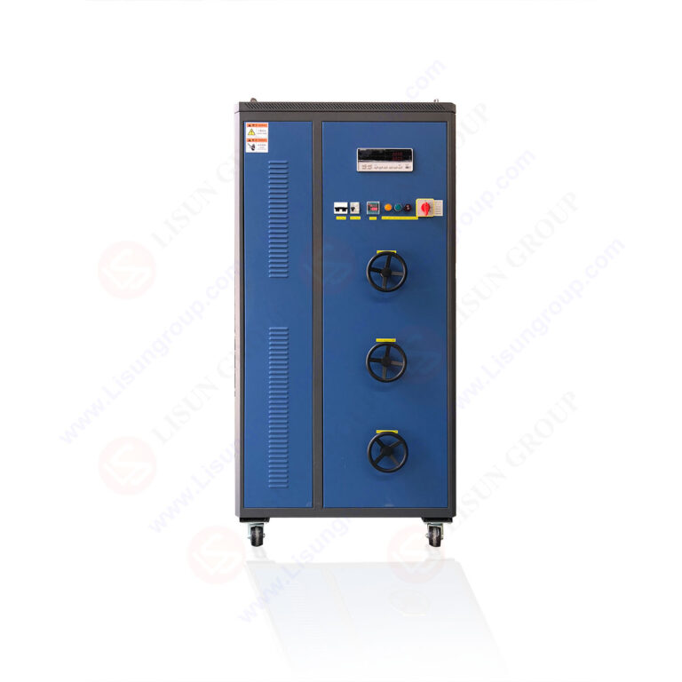
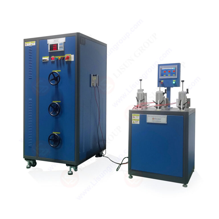
Instrumentation for Precision: The LISUN ZY-3 Needle Flame Tester
Accurate and reproducible execution of the needle flame test demands instrumentation of high precision and robust construction. The LISUN ZY-3 Needle Flame Tester is engineered to meet the exacting requirements of IEC 60695-11-5, GB/T 5169.5, and related standards. Its design integrates critical features to ensure testing fidelity.
The core of the ZY-3 system is its precision gas flow control and burner assembly. A high-quality needle valve and flow meter enable fine adjustment of the gas (typically 99% purity methane) to produce the standardized 12±1 mm high flame. The burner needle is crafted from stainless steel to resist corrosion and maintain a consistent orifice diameter, a factor directly influencing flame stability and thermal output. The specimen is mounted on a fully adjustable, three-dimensional positioning frame, allowing the operator to align the test flame with sub-millimeter accuracy to any point on a unit under test, be it a complex automotive sensor housing or a miniature medical device connector.
The test chamber is constructed from stainless steel and features a large, tempered glass observation window, facilitating clear viewing and recording of the test process. An internal black background enhances visual contrast for flame observation. Integrated safety features are comprehensive, including a gas leak detection and alarm system, automatic gas shut-off, and robust fire-resistant construction. The inclusion of a standardized timing unit automates the test and flame application durations, removing a potential source of operator error.
Key Specifications of the LISUN ZY-3 Needle Flame Tester:
- Standards Compliance: IEC 60695-11-5, GB/T 5169.5, ISO 9773 (for small parts), and referenced in end-product standards (IEC 62368-1, IEC 60950-1, IEC 60065, etc.).
- Flame Height: Adjustable 12±1 mm (calibrated via a proprietary gauge block).
- Gas Supply: 99% purity methane (or other specified gases), with precision pressure regulation.
- Timer Range: 0~99.99 seconds, with independent settings for flame application and post-application observation.
- Positioning: Three-dimensional adjustable specimen holder and burner mount.
- Chamber: Stainless steel body, tempered glass viewing window, black interior background.
- Safety Systems: Gas leak alarm, automatic shut-off, forced exhaust.
The competitive advantage of the ZY-3 lies in its synthesis of precision, durability, and user-centric design. The precise flame control ensures compliance with the standard’s nominal 1W power assertion, a parameter often variable in less refined instruments. The robust positioning system guarantees repeatable flame impingement, a non-negotiable requirement for comparative material or component qualification. For industries ranging from aerospace (testing wire harness components) to medical devices (assessing handpiece housings), this reliability translates directly into trustworthy hazard assessment data, supporting robust safety engineering and compliance certification.
Integration with Broader Fire Hazard Assessment Frameworks
The needle flame test is not an isolated procedure but a integral component within a hierarchical fire hazard engineering strategy. It occupies a specific niche in assessing resistance to small ignition sources, complementing other tests that measure different properties.
- Glow-Wire Tests (IEC 60695-2-10/11/12/13): These evaluate ignition and flame spread resistance from heated elements (e.g., overloaded resistors or glowing contacts), simulating different severity levels. While the glow-wire applies a hotter, but flameless, thermal source, the needle flame test adds the convective and chemical kinetic effects of a small flame.
- Horizontal/Vertical Flame Tests (UL 94, IEC 60695-11-10/20): These are material screening tests best suited for comparing the inherent flammability of polymeric materials. The needle flame test is more applied, focusing on the fire hazard of a finished article or component in a specific configuration.
- Heat Release Calorimetry (e.g., Cone Calorimeter per ISO 5660): This provides fundamental fire property data (heat release rate, smoke production) for material development. The needle flame test is a simpler, more cost-effective end-product verification tool.
A comprehensive safety dossier for a product, such as an industrial programmable logic controller (PLC) or an office multifunction printer, may incorporate data from multiple test types. The needle flame test would specifically validate that a small flame from a failing capacitor or relay inside the enclosure does not cause the external housing to ignite or propagate fire to adjacent wiring.
Industry-Specific Applications and Compliance Pathways
The application of advanced needle flame testing is mandated or strongly recommended across a vast spectrum of industries through their governing safety standards.
- Electrical & Electronic Equipment / Consumer Electronics / Office Equipment: IEC 62368-1, the hazard-based safety standard for audio/video, information, and communication technology equipment, explicitly references the needle flame test (from IEC 60695-11-5) to evaluate the fire hazard of enclosures, parts within enclosures, and components subjected to fault conditions.
- Automotive Electronics: ISO 20653 (Road vehicles — Degrees of protection) and various OEM specifications require testing of components for protection against flames from small sources. Electronic control units (ECUs), sensors, and wiring harness components are typical candidates.
- Household Appliances: Standards like IEC 60335-1 series call for testing to ensure that abnormal operation or component failure does not create a fire risk. The needle flame test is applicable to plastic parts near heat sources or electrical connections.
- Lighting Fixtures: IEC 60598-1 includes requirements for resistance to flame from a small source for parts supporting live components or those made of flammable materials.
- Medical Devices: IEC 60601-1, the general safety standard, requires that electrical medical equipment not pose a fire hazard. Components and enclosures may be subject to needle flame testing as part of a risk management file.
- Aerospace and Aviation: While governed by stringent FAA and EASA regulations, industry specifications often adopt or adapt IEC methods for testing non-metallic materials and components used in cabin interiors and electronic bays.
- Telecommunications Equipment: Similar to general IT equipment, telecom switches, routers, and base station components are evaluated per IEC 62368-1 or legacy standards like IEC 60950-1, which incorporate the needle flame test.
- Electrical Components: Switches, sockets, connectors, and terminal blocks are frequently tested to ensure that arcing or overheating within the device does not ignite the surrounding housing.
The Evolution of Standards and Future Trajectories
Fire testing standards are dynamic documents, evolving in response to new materials, technologies, and forensic insights from real-world failures. The current trend is towards greater harmonization of international standards (e.g., the adoption of IEC 60695 series globally) and a stronger emphasis on hazard-based safety engineering (HBSE), as exemplified by IEC 62368-1. This philosophy moves beyond prescriptive testing to a risk management process where tests like the needle flame are applied based on a quantified assessment of potential ignition sources and consequences.
Future advancements may see increased integration of sensor technology into test apparatus. High-speed thermography could map surface temperature spread during testing, while mass loss calorimetry could be miniaturized to provide quantitative heat release data from a needle flame test. Furthermore, computational fire modeling (Fire Dynamics Simulator – FDS) is beginning to use data from small-scale tests to predict component-level fire growth, creating a feedback loop where physical testing validates and refines digital twins.
Conclusion
The assessment of fire hazards in modern engineered products requires a sophisticated, multi-faceted approach. The needle flame test, as standardized in IEC 60695-11-5, represents a critical advanced methodology for simulating low-energy, fault-condition ignition events that are not adequately addressed by traditional flammability tests. Its rigorous application, supported by precise instrumentation such as the LISUN ZY-3 Needle Flame Tester, provides essential data for engineers and certifiers across the electrical, electronic, automotive, and aerospace industries. By integrating this test into a broader hazard-based safety framework, manufacturers can achieve a more robust and realistic evaluation of product fire safety, ultimately contributing to enhanced protection for persons, property, and infrastructure.
FAQ: Needle Flame Testing and the LISUN ZY-3 Tester
Q1: What is the primary difference between a needle flame test and a standard UL 94 V-0 test?
A1: UL 94 V-0 is a material classification test that subjects a vertically oriented bar specimen to a larger Bunsen burner flame (twice for 10 seconds each) to assess its ability to self-extinguish. It ranks materials based on their inherent flammability. The needle flame test is a product-oriented fault condition test. It applies a much smaller, calibrated flame (typically for 30s) to a specific point on an actual component or assembly to simulate a small internal ignition source. A material can be rated V-0 yet still fail a needle flame test if its configuration or wall thickness allows flame spread from a localized impingement.
Q2: For which types of components is the needle flame test particularly crucial?
A2: The test is especially critical for components where a small internal fault could generate a localized flame. This includes plastic enclosures for electronic control units (ECUs), connectors and sockets, small switches, wire insulation and cable ties, internal baffles or partitions within equipment, and any non-metallic part in close proximity to heat-generating or arcing components (e.g., near power supplies, relays, or motor controllers).
Q3: How is the 1W power assertion for the needle flame calibrated and verified on the LISUN ZY-3?
A3: The nominal 1W power is a function of the specific gas (methane), its flow rate, and the resulting flame geometry and temperature. Calibration is achieved indirectly but precisely by controlling these parameters. The operator uses the ZY-3’s precision flow meter to adjust the gas to the rate specified in the standard. The flame height is then set to 12±1 mm using the supplied calibration gauge. The combination of the correct gas flow and the verified flame height, produced by the standardized burner needle, ensures the thermal output conforms to the requirements of IEC 60695-11-5.
Q4: Can the ZY-3 tester be used for other small flame tests referenced in different standards?
A4: Yes, while optimized for IEC 60695-11-5 and GB/T 5169.5, the fundamental principle of a controlled small flame is common to several tests. With appropriate configuration and adherence to the specific standard’s parameters (e.g., flame height, application time, gas type), the ZY-3 can be adapted for related procedures, such as those described in certain clauses of ISO 9773 for small parts or in various automotive and aerospace internal standards that derive from the same core methodology.
Q5: What are the critical factors for ensuring repeatable and compliant test results?
A5: Key factors include: 1) Gas Purity: Use of 99% or higher purity methane as stipulated. 2) Flame Calibration: Meticulous adjustment of flow rate and verification of flame height before each test session. 3) Specimen Conditioning: Storing and preparing specimens as mandated by the end-product standard (often at 23±2°C and 50±5% RH for 24+ hours). 4) Precise Positioning: Using the 3D adjustment to ensure the flame tip contacts the exact test point as defined in the product’s test plan. 5) Controlled Environment: Performing tests in a draft-free lab and using the apparatus’s enclosed chamber to prevent air currents from affecting the flame.