


Advancements in Simulated Fault Condition Testing for Material and Component Safety
The relentless evolution of modern technology, characterized by increasing power densities, miniaturization, and the proliferation of complex electronic systems across diverse sectors, has precipitated a parallel escalation in fire safety requirements. Traditional flammability tests, while foundational, often fail to replicate the precise, high-energy fault conditions that can occur in real-world applications. Consequently, the industry has witnessed a significant shift towards more sophisticated, simulation-based testing methodologies. These advanced methods provide a critical bridge between controlled laboratory environments and the unpredictable nature of electrical and thermal faults, offering unparalleled insights into the fire-initiating potential of materials and components. This technical discourse examines the principles, applications, and instrumental implementations of these advanced techniques, with a particular focus on needle flame testing as a paramount example of fault condition simulation.
The Imperative for Fault Simulation in Product Safety Evaluation
Conventional flammability tests, such as the UL 94 vertical or horizontal burn tests, are designed to assess the ignitability and burning behavior of materials under a standardized flame impingement. These tests provide valuable comparative data on material properties. However, they operate under a fundamental limitation: they do not simulate the specific origin characteristics of many real fires in electrotechnical equipment. Faults such as overheated components, poor electrical connections, arcing, or failed insulation can generate highly localized, intense thermal energy sources that behave differently from a laboratory Bunsen burner flame.
The thermal insult from a fault is often transient, of varying intensity, and directed at a specific, vulnerable point on a component—such as a wire junction, a capacitor body, or a printed circuit board (PCB) trace. A material that performs adequately under a broad, steady flame may fail catastrophically when subjected to this type of pinpoint, high-temperature exposure. Therefore, the engineering philosophy has moved beyond merely assessing if a material burns, to rigorously evaluating how a complete assembly or sub-assembly responds to a credible internal ignition source. This paradigm shift is codified in international safety standards, including the IEC 60695-2-2 series, which governs glow-wire and needle-flame tests, mandating that safety engineering must account for potential fault conditions within the equipment itself.
Principles and Mechanics of Needle Flame Testing
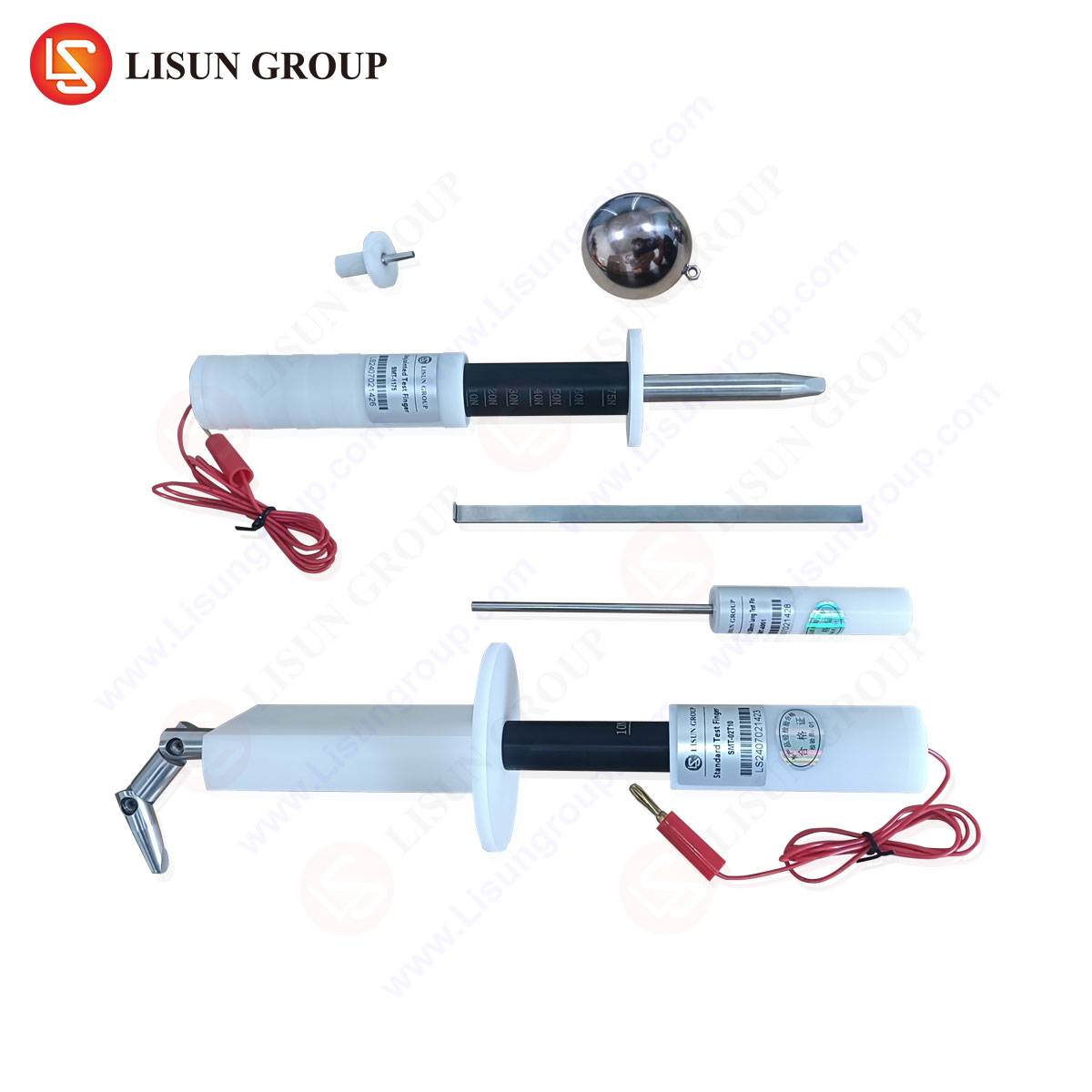
The needle flame test stands as a quintessential methodology for simulating the effect of small, localized flames that may result from faulty conditions. Its core principle involves the application of a defined, small-scale flame from a specified burner to a test specimen, under controlled laboratory conditions, to assess the resulting fire hazard. The test flame is typically generated by a 100% butane gas burner with a nozzle orifice of 0.5 mm ± 0.1 mm, producing a nominal flame height adjustable to 12 mm ± 1 mm. This configuration generates a flame with a total energy output approximating 35W, deliberately chosen to replicate the energy potential of a severe fault.
The testing protocol is meticulous. The specimen, which can be a complete end-product, a sub-assembly, or a representative section thereof, is mounted in a prescribed orientation within a draft-protected enclosure. The needle flame is applied to the predetermined, most vulnerable point for a strictly defined period, usually 30 seconds. Following flame application, critical observations are recorded: the duration of any subsequent flaming or glowing combustion of the specimen, the extent of flame spread, and whether burning debris (which can act as secondary ignition sources) detach and ignite a surgical cotton indicator placed below. The pass/fail criteria are stringent, typically requiring self-extinguishment within a short timeframe after flame removal and the absence of hazardous flame spread or ignition of the indicator.
This test does not merely evaluate material properties in isolation; it assesses the integrated fire response of a system. It reveals how adjacent materials interact, whether enclosures contain or propagate fire, and if design features like barriers, venting, or material selection effectively mitigate the consequences of a localized fault. The data derived is both qualitative and quantitative, informing design iterations, material selection, and ultimately, certification against critical safety standards.
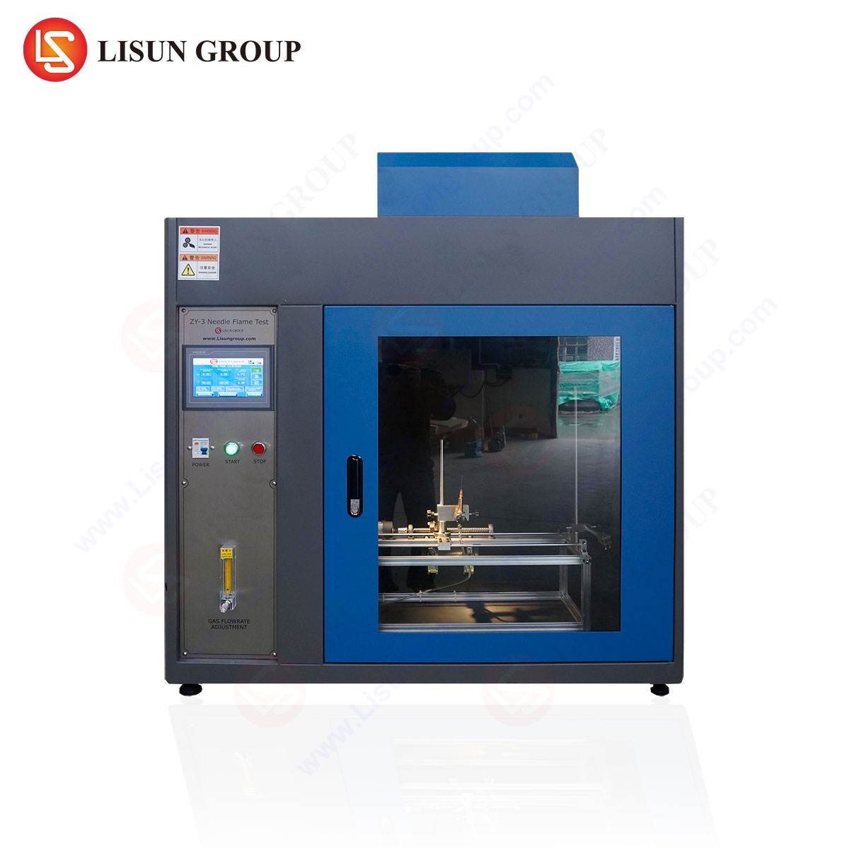
Instrumentation for Precision Fault Simulation: The LISUN ZY-3 Needle Flame Tester
The fidelity and repeatability of needle flame testing are wholly dependent on the precision and reliability of the instrumentation employed. The LISUN ZY-3 Needle Flame Tester exemplifies the engineering required to meet the exacting demands of contemporary standards such as IEC 60695-11-5, GB/T 5169.5, and related norms. This apparatus transforms the theoretical test protocol into a consistent, measurable, and auditable process.
The ZY-3 system is engineered around core specifications that ensure methodological rigor. Its burner assembly provides precise control over gas flow to maintain the stipulated 12mm flame height. A key feature is the integrated flame temperature verification system, often utilizing a thermocouple-based calibration procedure to confirm the flame’s thermal output conforms to the required 1000°C ± 50°C at a defined reference point. The test chamber is constructed from durable, non-reflective materials with a transparent observation window, and includes a regulated airflow system to maintain draft-free conditions as mandated. The specimen holder is fully adjustable, allowing for precise positioning of the test flame at angles of 0°, 20°, or 45° relative to the specimen, accommodating a wide range of product geometries and potential fault locations.
Automation and safety are integral to its design. Modern units like the ZY-3 often incorporate programmable logic controllers (PLCs) to manage test sequences—controlling flame application duration, retraction, and post-application observation timers with high accuracy. This minimizes operator variance and enhances repeatability. Safety interlocks, gas leak detection, and automatic gas shut-off valves are standard, protecting both the operator and the laboratory environment. Data logging capabilities allow for the storage of test parameters, timings, and observations, facilitating comprehensive reporting and traceability for quality assurance and certification audits.
Cross-Industry Application of Simulated Fault Testing
The utility of advanced flammability testing via needle flame simulation spans the entire spectrum of modern manufacturing, wherever electrical energy is utilized.
- Electrical and Electronic Equipment & Industrial Control Systems: Here, the test is applied to enclosures, wiring ducts, terminal blocks, and PCB assemblies. It evaluates whether a fault on a crowded control board, for instance, would be contained within a plastic housing or lead to the ignition of adjacent wire harnesses.
- Household Appliances and Consumer Electronics: Components like power supply units, internal connectors, motor windings, and remote control casings are tested. The goal is to ensure that a fault in a washing machine’s controller or a television’s switch-mode power supply does not escalate into a full enclosure fire.
- Automotive Electronics: With the automotive industry’s move towards 48V systems and greater electrification, testing components like battery management system (BMS) housings, sensor connectors, and infotainment systems is critical. The test simulates a short-circuit event in the harsh, vibration-prone automotive environment.
- Lighting Fixtures: Particularly for LED drivers and plastic luminaire housings, the needle flame test assesses the risk associated with faulty ballasts or overheating components igniting the fixture body or its mounting materials.
- Telecommunications Equipment and Office Equipment: Network switches, router housings, server components, and plastic parts of printers/copiers are evaluated to guarantee that a fault in a continuously operating device in an office or data center does not become a fire origin point.
- Medical Devices and Aerospace Components: For these highly regulated fields, testing is applied to non-metallic enclosures, control panels, and internal components of devices ranging from patient monitors to in-flight entertainment systems. The extreme consequence of failure in these environments demands the highest level of fault tolerance verification.
- Electrical Components and Cable Systems: Switches, sockets, and especially the insulation and jacketing of wires and cables are tested to confirm that a localized overheating event at a connection point will not cause the cable to act as a “fuse” propagating flame along its length.
Quantitative Metrics and Standards Compliance
The output of a needle flame test is not merely a pass/fail result but a set of quantitative metrics that feed into engineering analysis. Key measured parameters include:
- Duration of Flaming Combustion (tf): The time from removal of the test flame to the cessation of all flaming on the specimen.
- Duration of Glowing Combustion (tg): The time from the cessation of flaming to the end of all glowing.
- Total Flaming Duration: Often the sum of application time and tf.
- Extent of Damage: The measured length or area of material consumed or charred beyond a specified limit.
- Ignition of Indicator: A binary result indicating whether burning droplets or particles ignited the cotton wool below.
Compliance with international standards is the primary objective. The test conditions, pass/fail criteria, and specimen preparation are meticulously detailed in standards such as:
- IEC 60695-11-5: Ed. 2.0 (2016) – Fire hazard testing – Part 11-5: Test flames – Needle-flame test method – Apparatus, confirmatory test arrangement and guidance.
- GB/T 5169.5: The Chinese national standard technically aligned with IEC 60695-11-5.
- UL 746A, IEC 60335-1, IEC 60950-1 (superseded by 62368-1): These end-product safety standards frequently cite the needle flame test as a normative requirement for evaluating fault conditions in specific components.
Manufacturers leverage data from instruments like the LISUN ZY-3 to generate compliance reports for these standards, which are essential for achieving global market access, from CE marking and UL certification to CCC (China Compulsory Certification).
Strategic Advantages of Integrated Testing Systems
Deploying a dedicated, advanced testing system like the needle flame tester confers several strategic advantages beyond basic compliance. Firstly, it enables pre-compliance and design-for-safety workflows. Engineering teams can identify fire safety vulnerabilities early in the product development cycle, allowing for cost-effective design modifications before costly tooling is committed or certification tests are failed. Secondly, it provides comparative data for material and supplier selection. By testing components from different suppliers or alternative material grades, engineers can make objective, safety-driven sourcing decisions. Thirdly, it enhances quality assurance and failure analysis. Periodic testing of production samples can monitor consistency, while the test can be used diagnostically to investigate field failure returns and understand the root cause of thermal events.
The competitive edge lies in the depth of safety assurance. A product validated through rigorous fault simulation testing carries a demonstrably lower real-world fire risk. This reduces liability, strengthens brand reputation for safety and quality, and meets the increasingly stringent due diligence requirements of insurers, regulators, and large corporate purchasers. In industries like automotive and aerospace, where supplier qualifications are exhaustive, possessing in-house capability for such tests is often a prerequisite for becoming an approved vendor.
Future Trajectories in Flammability Assessment
The trajectory of flammability testing continues to advance in tandem with technology. Emerging trends include the integration of advanced diagnostics into test apparatus. High-speed thermal imaging cameras can map heat spread in real-time, while evolved gas analysis (EGA) coupled with the test can identify toxic gas species produced during fault-induced combustion. Furthermore, there is a growing emphasis on multi-stress testing, where the flame insult is applied concurrently with or subsequent to other environmental stresses such as vibration, thermal cycling, or humidity exposure, more accurately simulating the conditions leading to a fault.
Computational modeling (Finite Element Analysis for fire propagation) is also beginning to complement physical testing. While not a replacement, validated models can help optimize test matrices and predict failure modes. The role of physical test apparatus like the needle flame tester will evolve to provide the critical empirical data required to calibrate and validate these sophisticated digital models, creating a hybrid approach to fire safety engineering that is both predictive and empirically grounded.
In conclusion, the move towards advanced flammability testing methods, epitomized by the needle flame test, represents a maturation of product safety philosophy from passive material assessment to active fault simulation. By rigorously challenging products with credible ignition scenarios derived from real failure modes, these methods provide a far more robust and meaningful assessment of fire hazard. Instruments engineered to exacting standards, such as the LISUN ZY-3 Needle Flame Tester, are indispensable in this endeavor, providing the precision, repeatability, and data integrity required to navigate the complex landscape of international safety compliance and to engineer inherently safer products for the global market.
FAQ: Needle Flame Testing and the LISUN ZY-3 Tester
Q1: What is the primary distinction between a needle flame test and a standard UL 94 V-0 test?
A1: The UL 94 V-0 test is a material-level test that classifies the burning behavior of a vertical bar of plastic under a specified Bunsen burner flame. It ranks materials based on their self-extinguishing time. The needle flame test is a fault simulation test performed on an end-product, sub-assembly, or component in its final form. It uses a smaller, more intense flame applied to a specific point to simulate a localized electrical fault, assessing the integrated fire response of the product’s construction, not just its base material properties.
Q2: For which specific components within an automotive electronics control unit (ECU) would needle flame testing be mandated?
A2: Testing would typically be focused on non-metallic parts that could be exposed to an internal fault. This includes the plastic housing or cover of the ECU itself, internal connector bodies, any plastic brackets, and areas of the printed circuit board (PCB), especially near high-current traces or power components. Standards like ISO 20653 (ingress protection) and various OEM-specific specifications often reference such tests for housings.
Q3: How does the LISUN ZY-3 ensure the consistency and accuracy of the test flame?
A3: The ZY-3 incorporates several design features for flame consistency. It uses a precision metering valve and gauge for repeatable gas (butane) flow control. Crucially, it includes a calibration function to verify the flame temperature using a supplied thermocouple. The apparatus allows the operator to measure the temperature of the flame at a fixed distance from the burner tip, adjusting the gas flow until it meets the standard’s requirement (e.g., 1000°C ± 50°C). This quantitative verification is essential for audit compliance.
Q4: Can the needle flame test be used on finished products with internal power sources, such as a battery-powered medical device?
A4: Testing of products with internal energy sources requires extreme caution and is generally not performed under standard conditions due to the risk of explosion or uncontrolled energy release. The standard methodology typically requires testing to be conducted on unpowered specimens. The simulated fault is the external needle flame itself. If assessment of an internal battery fault is needed, a different test standard (e.g., involving battery crush or overcharge) would be applicable.
Q5: What are the typical pass/fail criteria referenced in product safety standards when using this test?
A5: While criteria can vary slightly by end-product standard, common requirements are: 1) Flaming combustion of the specimen must self-extinguish within 30 seconds after removal of the test flame. 2) The specimen must not burn up to a fixed marker line (usually 150mm above the application point). 3) No burning droplets or particles fall from the specimen that ignite a surgical cotton indicator placed 200mm ± 5mm below the test point. Full compliance requires meeting all applicable criteria specified in the relevant clause of the safety standard for the product.