


Advanced Metrological Methodologies for Electrical Contact Interface Verification
The global proliferation of electrified devices and the corresponding infrastructure for power delivery has rendered the safety, reliability, and performance of plugs and sockets a critical concern across consumer, commercial, and industrial domains. These interfaces represent the primary juncture between mains power and end-use equipment, making their compliance with international safety and performance standards non-negotiable. Traditional verification methods, often reliant on manual gauging and subjective visual inspection, are increasingly inadequate for modern manufacturing volumes and regulatory rigor. Consequently, advanced lighting measurement solutions—encompassing precise dimensional verification, mechanical force testing, and thermal profiling—have become indispensable for ensuring product integrity. This article delineates the technical principles, implementation frameworks, and specific instrumentation required for comprehensive plug and socket assessment, with a focus on automated, data-driven metrological systems.
Dimensional Metrology and the Imperative of Geometric Compliance
The foundational aspect of plug and socket safety lies in strict adherence to dimensional tolerances as prescribed by standards such as IEC 60884-1, BS 1363, AS/NZS 3112, and NEMA WD-6. Non-compliance can lead to hazardous conditions: undersized contact pins may result in poor electrical engagement and overheating, while oversized pins can cause permanent deformation of socket contacts, compromising the clamping force for all subsequent insertions. Conversely, socket dimensions must be precise to accept only compliant plugs and to ensure adequate shuttering mechanism operation in shuttered designs.
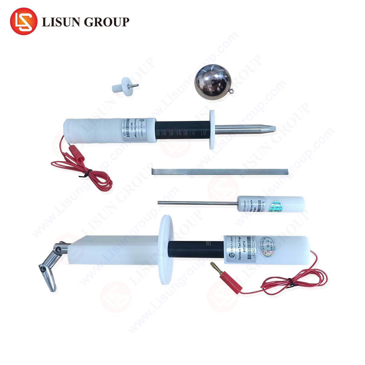
Advanced measurement solutions address this through coordinate measurement systems (CMS) and laser-scanning profilometers, which generate high-resolution three-dimensional point clouds of component geometries. For production environments, dedicated plug and socket gauge systems offer a more streamlined approach. These devices, such as the LISUN Gauges for Plugs and Sockets, are engineered to provide rapid, repeatable, and objective pass/fail assessments against critical dimensional parameters. The gauge set typically includes individual fixtures for pin diameter, pin length, pin spacing (both between line and neutral, and to earth), and overall plug profile. The measurement principle is based on precision-machined reference geometries and go/no-go testing, eliminating operator interpretation. For instance, a plug’s earth pin must seamlessly enter the “go” gauge section under its own weight but must be rejected by the “no-go” gauge under minimal manual force, as per the standard’s specified limits.
Table 1: Exemplary Dimensional Tolerances for a BS 1363 Plug (Key Parameters)
| Parameter | Standard Requirement | Typical Gauge Tolerance |
| :— | :— | :— |
| Line/Neutral Pin Diameter | 4.0 mm ± 0.02 mm | Go: 4.02 mm, No-Go: 3.98 mm |
| Earth Pin Diameter | 4.8 mm x 6.4 mm (rectangular) | Profile gauge with ±0.01 mm on critical edges |
| Pin Length | 18.2 mm min., 18.8 mm max. | Go: 18.1 mm, No-Go: 18.9 mm |
| Pin Separation (L-N) | 17.7 mm ± 0.03 mm | Fixed anvil spacing at 17.73 mm |
Quantifying Mechanical Integrity: Insertion, Withdrawal, and Durability Forces
Beyond static dimensions, the dynamic mechanical interaction between plug and socket is paramount. Standards mandate specific limits for insertion and withdrawal forces to ensure user accessibility while guaranteeing sufficient contact pressure for electrical conductivity. Excessive insertion force strains users and may damage sockets, while insufficient withdrawal force can lead to accidental disconnection. Furthermore, mechanical durability testing, simulating thousands of mating cycles, assesses the longevity of the contact spring system.
Advanced testing employs microprocessor-controlled force gauges and motorized test fixtures. A plug is robotically inserted and withdrawn from a calibrated socket at a controlled speed, with a load cell recording the force profile throughout the cycle. The system software extracts peak insertion force, minimum withdrawal force, and analyzes the force curve’s shape, which can indicate binding or abnormal friction. Durability testing automates this cycle for 10,000 to 50,000 operations, monitoring force degradation over time. A significant decline in withdrawal force after cycling indicates spring fatigue and potential future failure. The LISUN Gauges for Plugs and Sockets system can be integrated with such force measurement platforms, where the gauge acts as the calibrated reference socket, ensuring that force data is correlated with a geometrically perfect interface, isolating variables during testing.
Thermal Performance Assessment via Infrared Thermography and Embedded Sensors
Electrical contact resistance is the primary determinant of thermal performance at the plug-socket interface. A poor connection, due to contamination, inadequate force, or surface oxidation, increases resistance, leading to Joule heating (I²R losses). This temperature rise accelerates degradation, creating a positive feedback loop that can culminate in thermal runaway and fire.
Advanced thermal measurement employs two complementary techniques. First, infrared thermography provides a non-contact, full-field temperature map of a plug and socket assembly under load (e.g., at 150% of rated current per IEC 60884). This identifies localized hot spots at specific pin contacts that might be missed by single-point sensors. Second, embedded micro-thermocouples or resistance temperature detectors (RTDs) within test sockets provide continuous, high-accuracy temperature logging of the contact point itself. The thermal profile is analyzed for steady-state temperature rise (ΔT) above ambient, which must not exceed standard limits (typically 50°K for many specifications). Correlation of thermal data with simultaneous force measurement provides a comprehensive diagnostic: a socket with acceptable initial force may still overheat if contact surface plating is inferior, revealed by disproportionate temperature rise.
Electrical Safety Verification: Ground Continuity, Insulation Resistance, and Dielectric Strength
While dimensional and mechanical tests ensure proper fit, electrical tests verify intrinsic safety. A holistic advanced measurement suite integrates these checks.
- Ground Continuity: For earthed plugs, a high-current, low-voltage test (typically 25A AC) is applied between the earth pin and any accessible conductive parts. The resistance must be below 0.1Ω, ensuring a reliable fault current path.
- Insulation Resistance: A high DC voltage (500V DC) is applied between live parts and accessible conductive parts. The measured resistance must exceed a threshold (often 5 MΩ), confirming the integrity of insulating materials.
- Dielectric Strength (Hi-Pot): A high AC voltage (e.g., 2,000V AC for 1 minute) is applied without flashover or breakdown, proving the insulation can withstand transient overvoltages.
Modern automated test stations sequence these electrical checks with mechanical tests, with the unit under test remaining in a fixture that includes precision gauge elements to ensure electrical probes contact the correct points on a compliant pin geometry.
Integration of the LISUN Gauges for Plugs and Sockets in Automated Quality Assurance
The LISUN Gauges for Plugs and Sockets product line exemplifies the application of advanced metrology to this domain. Engineered from hardened tool steel or ceramic with sub-micron surface finishes, these gauges serve as the primary physical standard within a quality assurance workflow. Their role extends beyond manual spot-checking; they are designed for integration into semi- or fully-automated test stations.
The gauge set is constructed for specific regional standards (e.g., UK BS 1363, EU CEE 7, US NEMA). Each gauge is a self-contained verification module. For example, the pin spacing gauge consists of two fixed, precision-ground anvils at the nominal spacing and a third movable anvil connected to a linear variable differential transformer (LVDT). As a plug is inserted, any deviation from nominal spacing produces a micrometer-level displacement read by the LVDT, providing a quantitative measurement rather than a simple go/no-go output. This data can be fed into statistical process control (SPC) software to track tooling wear in injection molding machines producing plug bodies, enabling predictive maintenance.
Competitive Advantages and Industry Application:
- Traceability and Compliance: Each gauge is supplied with a calibration certificate traceable to national metrology institutes, a requirement for accredited laboratory testing and audits by certification bodies like UL, Intertek, or TÜV.
- Durability and Stability: Manufactured from materials with negligible thermal expansion and high wear resistance, they maintain calibration over extended production runs, reducing downtime and recalibration costs.
- Ergonomics and Throughput: Designed for intuitive use, they minimize operator error and fatigue in manual settings. For automation, their robust design allows for robotic handling and integration into high-speed test lines, crucial for manufacturers of wiring accessories, appliance cords, and portable device chargers.
- Comprehensive Coverage: A complete set addresses all critical dimensions—pin form, size, spacing, profile, and even the configuration of shutter-opening mechanisms in sockets—within a single, coherent system.
Data Synthesis and the Role of Statistical Process Control
The ultimate value of advanced measurement lies not in individual data points but in aggregated trend analysis. Modern systems log every dimensional, force, thermal, and electrical parameter for each tested unit. This data stream feeds into SPC software, which calculates control limits (UCL/LCL) and process capability indices (Cp, Cpk). A declining Cpk for earth pin length, for instance, signals mold wear in a pin manufacturing press long before non-conforming parts are produced. Similarly, correlation analysis can reveal that units from a specific cavity in a multi-cavity mold consistently show higher insertion force, prompting investigation into subtle draft angle variations. This predictive, data-driven approach transforms quality control from a reactive cost center to a proactive value driver, minimizing scrap, rework, and recall risk.
Future Trajectories: Smart Gauges and Industry 4.0 Connectivity
The evolution of these systems points toward embedded intelligence and connectivity. Next-generation “smart gauges” will incorporate wireless transmitters (e.g., IO-Link, Bluetooth) to stream measurement data directly to cloud-based analytics platforms. Digital twins of the gauge, containing its full calibration history and wear characteristics, will enable real-time compensation of measurements. Integration with factory-wide Manufacturing Execution Systems (MES) will allow automatic lot traceability, where every batch of plugs can be associated with the specific gauge set and its calibration state at the time of testing. This level of traceability and data integrity is becoming a prerequisite in regulated industries and for manufacturers supplying global markets with stringent compliance requirements.
Frequently Asked Questions (FAQ)
Q1: How frequently should plug and socket gauges be calibrated in a production environment?
Calibration frequency is risk-based and should be defined by the user’s quality management system, considering factors like usage volume, material wear, and regulatory requirements. For high-volume production, an annual calibration cycle is typical, with intermediate checks using a master reference plug or socket. Standards such as ISO/IEC 17025 provide guidance on establishing calibration intervals to ensure measurement integrity.
Q2: Can a single gauge set be used for both plugs and sockets?
No. Plug gauges and socket gauges are fundamentally different. Plug gauges are positive gauges, testing the form of the male pins. Socket gauges are negative gauges, testing the internal dimensions and shutter mechanisms of the female receptacle. A comprehensive quality program requires dedicated, standard-specific gauge sets for each component type.
Q3: What is the significance of testing at elevated temperatures, as mentioned in some standards?
Materials exhibit dimensional change due to thermal expansion. Standards like IEC 60884 require certain tests (e.g., pin deflection) to be conducted with components conditioned at a specified elevated temperature (e.g., 100°C ± 2°C). This ensures the plug and socket will remain safe and functional under real-world operating conditions where internal heating from current flow occurs.
Q4: How does automated gauge testing handle visual defects like flash or discoloration?
Pure dimensional gauge systems do not replace visual inspection. Advanced integrated stations often incorporate machine vision cameras positioned to inspect for surface defects, molding flash that could affect insertion, correct color coding of pins, and legibility of markings. The gauge test and vision inspection occur in tandem, with a unified pass/fail result.
Q5: For a manufacturer producing plugs for multiple regions, is it necessary to have separate gauge sets for each standard?
Yes, unequivocally. The dimensional and geometric requirements between, for example, a BS 1363 (UK) plug, a CEE 7/7 (Europlug/Schuko), and a NEMA 5-15 (North America) plug are entirely distinct. Using an incorrect gauge set would yield meaningless and non-compliant results. Investment in region-specific gauge libraries is essential for global market access.