


An Overview of AS/NZS 3112 and its Compliance Framework
The AS/NZS 3112 standard, formally titled “Approval and test specification—Plugs and socket-outlets,” constitutes the paramount regulatory document governing the safety, interoperability, and dimensional conformity of plugs and socket-outlets within Australia and New Zealand. Its purview extends to devices rated not exceeding 250 V AC and 20 A, establishing a foundational framework for electrical safety that impacts manufacturers, testing laboratories, certification bodies, and regulatory authorities. The standard’s primary objective is to mitigate risks associated with electric shock, fire hazards, and mechanical failure by specifying stringent requirements for construction, insulation, accessibility of live parts, and, critically, dimensional accuracy. It is within this context that the use of standardized gauges, such as the Gauge G1, becomes an indispensable component of the conformity assessment process, providing an unambiguous, quantitative method for verifying that manufactured components adhere to the stipulated dimensional tolerances.
The Specific Function and Design of the Gauge G1
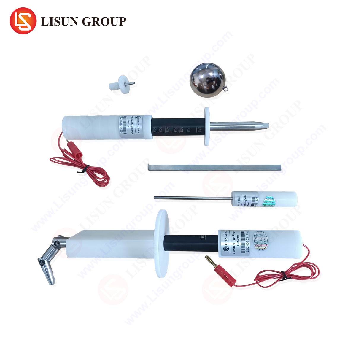
Gauge G1, as defined within the AS/NZS 3112 standard, is a precision-engineered tool designed explicitly for the verification of the dimensional compliance of socket-outlets. Its function is not to measure a continuous range of values but to perform a pass/fail assessment against the critical safety dimensions mandated by the standard. The gauge is engineered to simulate the insertion and withdrawal forces, as well as the geometric interface, of a compliant plug. Its design incorporates specific features that correspond to the key dimensional parameters of a socket-outlet’s contact tubes and shutters. A primary function is to ensure that the entry apertures and the internal contact tubes are of the correct size and profile to accept a standard plug without undue force or binding, while simultaneously preventing access to live parts by objects that do not conform to the plug’s pin configuration. The gauge’s construction from durable, dimensionally stable materials, such as hardened steel or high-strength engineering plastics, ensures its own longevity and measurement integrity over repeated use in quality control environments.
Critical Dimensional Parameters Verified by Gauge G1
The application of Gauge G1 provides a comprehensive check of several interdependent socket-outlet geometries. Key among these are the verification of the contact tube profiles for the active, neutral, and earth pins. The gauge confirms that the cross-sectional shape and internal dimensions of these tubes are within tolerance, ensuring adequate contact pressure and surface area for a safe electrical connection. Furthermore, it assesses the alignment and spacing between the contact tubes, a parameter crucial for preventing short circuits and ensuring correct plug orientation. Another vital parameter is the verification of the shutter mechanism operation. AS/NZS 3112 requires socket-outlets to be fitted with shutters that obstruct access to the active and neutral contact tubes unless an earth pin of a compliant plug is inserted first. Gauge G1 is designed to test the correct sequencing and force required to open these shutters, thereby validating this critical safety feature. The depth of insertion and the force required for both insertion and withdrawal are also implicitly tested, ensuring that a plug will mate securely without posing a risk of accidental disconnection or requiring excessive force that could damage the plug or socket.
Testing Principles and Procedural Application in Quality Assurance
The deployment of Gauge G1 within a quality assurance or certification testing regimen follows a rigorous, standardized procedure to ensure repeatable and reliable results. The testing principle is one of simulated use under controlled conditions. The gauge is manually or mechanically inserted into the socket-outlet under test with a specified force, not exceeding that which a typical user would apply. The insertion must proceed smoothly, without jamming or requiring excessive effort, and the gauge must seat fully into its intended position. Subsequently, the withdrawal force is assessed to ensure it falls within a range that guarantees a secure connection yet allows for safe removal. Crucially, the gauge is also used to verify that the socket-outlet correctly rejects non-compliant insertion attempts; for instance, attempting to insert the gauge without first engaging the earth pin simulation feature should not open the shutters. This binary pass/fail outcome provides a clear, objective determination of the socket-outlet’s conformance to the dimensional and mechanical safety clauses of AS/NZS 3112.
LISUN Gauges for Plugs and Sockets: Precision Instrumentation for Compliance
In the domain of compliance testing, the accuracy and reliability of the gauge itself are paramount. LISUN Gauges for Plugs and Sockets are engineered to meet this demand, providing instrumentation that faithfully replicates the geometries specified in international standards, including AS/NZS 3112 Gauge G1. These gauges are manufactured from high-grade materials, subject to stringent quality control during production to ensure their own dimensional tolerances are significantly tighter than those permitted for the products they are designed to test. This practice of “gauge maker’s tolerance” ensures that any measurement uncertainty introduced by the gauge is negligible. LISUN’s G1 gauge, for example, is precisely machined to verify the socket contact tube profiles, pin spacing, shutter operation, and insertion/withdrawal forces as mandated. The product specifications typically include detailed certification, often traceable to national metrology institutes, confirming its conformance to the reference dimensions laid out in the standard. This level of precision makes LISUN gauges a trusted tool in the laboratories of manufacturers and third-party certification bodies alike.
Industry Applications in Manufacturing and Certification
The application of Gauge G1 spans the entire lifecycle of a socket-outlet product, from initial design validation to mass production and post-market surveillance. During the Research and Development phase, engineers use the gauge to iteratively check prototype socket-outlets, ensuring that design drawings translate into physically compliant products before committing to production tooling. On the manufacturing floor, Gauge G1 serves as an essential tool for in-process quality control. Production line operators perform periodic checks on sampled units to detect any drift in the manufacturing process, such as tool wear in injection molding machines or misalignment in assembly jigs, that could lead to non-conforming products. For certification bodies like Standards Australia or external testing laboratories, the gauge is a fundamental part of the type-testing protocol. A socket-outlet cannot receive certification unless it successfully passes the Gauge G1 test, along with a suite of other electrical, thermal, and mechanical tests. This multi-tiered application underscores the gauge’s role as a cornerstone of product safety and market access.
Comparative Analysis of Gauge Verification Methodologies
While gauge testing provides a rapid and effective pass/fail assessment, it exists within a broader ecosystem of verification methodologies. The most fundamental distinction lies between go/no-go gauge testing and coordinate metrology. Gauge testing, as performed with the G1, is a qualitative check for conformance within a predefined tolerance zone. It is fast, cost-effective, and requires minimal operator training, making it ideal for high-frequency production line checks. In contrast, coordinate measuring machines (CMMs) and optical scanners provide quantitative, high-resolution data. These systems can generate a full 3D point cloud of a socket-outlet’s internal geometry, allowing engineers to determine not just if a part is non-compliant, but precisely how and where it deviates from the specification. This is invaluable for root cause analysis during R&D or failure investigation. However, CMM testing is slow, expensive, and requires a highly skilled operator. Therefore, the two methodologies are complementary: gauge testing is used for routine verification of conformance, while coordinate metrology is reserved for in-depth analysis and gauge calibration. The LISUN G1 gauge itself would be certified using such high-precision metrological equipment.
Integrating Gauge Testing with Comprehensive Safety Protocols
It is critical to recognize that dimensional verification with Gauge G1, while essential, represents only one facet of the complete safety assessment required by AS/NZS 3112. A compliant socket-outlet must also pass a battery of other tests, and the gauge test is often a prerequisite for many of them. For instance, the electrical endurance test, which subjects the socket-outlet to thousands of insertions and withdrawals of a test plug, relies on the initial dimensional conformance to ensure a valid test outcome. Similarly, the temperature rise test, which verifies that the socket-outlet does not overheat under load, assumes that the contact geometry is correct to establish proper electrical connection. Tests for resistance to heat, impact, and tracking, as well as rigorous checks on the integrity of insulation and earthing, form a holistic safety envelope. The G1 gauge test is thus the foundational mechanical check that enables the validity and safety of subsequent electrical and environmental tests.
Technical Specifications of a Representative Gauge System
A professionally manufactured Gauge G1, such as those supplied by LISUN, is characterized by a precise set of technical attributes. The following table outlines the typical specifications for a gauge designed to AS/NZS 3112 G1 requirements:
| Specification Category | Detail |
|---|---|
| Applicable Standard | AS/NZS 3112:2017 (and amendments) |
| Gauge Type | Go/No-Go, Socket-Outlet Verification |
| Material | Hardened Tool Steel or Dimensionally Stable Engineering Plastic |
| Calibration | Certified Traceable to National Measurement Standards |
| Verified Parameters | Contact Tube Profile (Active, Neutral, Earth), Pin Spacing, Shutter Operation, Insertion/Withdrawal Force |
| Finish | Corrosion-resistant, non-conductive coating where applicable |
| Documentation | Certificate of Conformance detailing measured dimensions against standard |
These specifications ensure that the gauge is not merely a piece of metal or plastic, but a calibrated measuring instrument whose own accuracy is rigorously assured.
Addressing Common Misconceptions in Dimensional Compliance
A prevalent misconception in the industry is that a plug that fits into a socket-outlet is de facto evidence of compliance. This is a dangerous assumption. A socket-outlet may accept a plug yet still be non-compliant due to undersized contact tubes leading to overheating, misaligned shutters that could be bypassed, or excessive insertion force that risks damage. The Gauge G1 is specifically designed to be more sensitive to these tolerances than a standard plug. Another misconception is that gauge testing is superfluous if a product is manufactured from certified molds or designs. In reality, material shrinkage, tool wear, and assembly variations can introduce significant deviations over a production run. Regular gauge testing is therefore a non-negotiable activity for maintaining consistent quality and safety throughout a product’s manufacturing lifecycle. The use of a LISUN gauge provides the objective evidence needed to counter these misconceptions with definitive data.
Frequently Asked Questions
What is the typical frequency for calibrating a LISUN G1 gauge in a high-volume production environment?
Calibration frequency is risk-based. In a high-volume manufacturing setting where the gauge is used frequently, an annual calibration cycle is a common industry practice. However, this should be supported by regular intermediate checks using a master socket or other reference artifact to detect any premature wear or damage. The specific frequency should be defined in the laboratory’s or factory’s quality management system.
Can the LISUN G1 gauge be used to test socket-outlets from other regions or standards?
No. The LISUN G1 gauge is meticulously engineered to the exact dimensions specified in AS/NZS 3112. Plug and socket systems from other regions (e.g., North America’s NEMA 5-15, Europe’s CEE 7/7) have entirely different pin configurations, sizes, and safety requirements. Using an incorrect gauge will yield meaningless results and fails to assure safety. A dedicated gauge specific to each standard is required.
What is the consequence of a socket-outlet failing the G1 gauge test during production?
A failure constitutes a major non-conformity. The immediate action is to quarantine all units from the affected production batch. A root cause analysis must be initiated to identify the source of the deviation, such as worn tooling, a faulty component, or an assembly error. The manufacturing process must be corrected before production can resume, and previously produced units may need to be rechecked or recalled depending on the severity and extent of the non-conformance.
How does the verification of shutter operation with the G1 gauge enhance safety?
The shutter mechanism is a primary defense against electric shock, particularly for children. The G1 gauge verifies that the shutters for the active and neutral contact tubes cannot be opened without the simultaneous insertion of an earth pin simulator. This ensures that a child cannot, for example, insert a single metal object like a paperclip into a single contact tube and make contact with a live part. The gauge tests both the sequencing and the force required, validating this critical protective feature.