


Comprehensive Evaluation of Attachment Plug and Receptacle Integrity: Methodologies, Standards, and Instrumentation
The reliable operation of electrical attachment plugs and receptacles constitutes a fundamental pillar of electrical safety and performance across residential, commercial, and industrial environments. These interface components are subject to continuous mechanical stress, environmental exposure, and electrical load, making their conformity to design and safety standards non-negotiable. Systematic testing, therefore, transitions from a quality assurance step to a critical risk mitigation procedure. This article delineates the core testing paradigms for plugs and sockets, examining the underlying principles, referencing pertinent international standards, and analyzing the role of specialized gauging systems in ensuring dimensional and functional compliance.
Dimensional Conformance: The Foundation of Mechanical Safety and Interoperability
Prior to any electrical validation, the geometric integrity of plugs and receptacles must be rigorously verified. Dimensional non-conformance can lead to a cascade of failure modes: poor contact engagement increases resistance and overheating; loose mating creates arcing hazards; and deviations in pin spacing or shield dimensions can compromise user safety or damage equipment. Testing in this domain is primarily comparative, assessing physical specimens against the tolerances defined in standards such as IEC 60884-1, BS 1363, or NEMA WD-6.
The process involves verifying critical parameters: the precise dimensions and spacing of live, neutral, and earth pins (including length, diameter, and center-to-center distances); the configuration and size of the socket aperture and shutter mechanisms; and the overall plug profile and cord guard dimensions. Gauges employed for this purpose are not simple measuring devices but are legally defined “go/no-go” instruments. A “go” gauge, representing the maximum permissible material condition, must fit appropriately, while a “no-go” gauge, representing the minimum permissible condition, must not fit. This binary assessment ensures components fall within the safe interoperability envelope, preventing the use of undersized pins or oversized socket entries that could lead to hazardous partial insertion.
Evaluating Mechanical Endurance Through Standardized Stress Cycles
Attachment plugs and receptacles are designed for a specified service life, quantified in mating cycles. Mechanical endurance testing simulates this lifespan under controlled, accelerated conditions to predict field performance and identify design weaknesses. The test apparatus typically comprises an automated rig that engages and disengages a plug from a receptacle thousands of times, often under a prescribed electrical load.
The standard methodology, outlined in clauses like those in IEC 60884-1, requires the sample to withstand a minimum number of cycles—commonly 5,000 for general-use devices—without mechanical failure. Post-test evaluation is multifaceted. Assessors check for cracking or deformation of insulating bodies, wear on current-carrying contacts that could degrade electrical performance, integrity of the earthing connection, and proper continued operation of any protective shutters. The rate of cycling, the insertion/withdrawal force profile, and the alignment mechanism of the test rig are all calibrated to ensure repeatable and reproducible results that accurately reflect real-world wear patterns, excluding anomalous failures due to misaligned test equipment.
Thermal Stress and Overcurrent Behavior Under Controlled Laboratory Conditions
Electrical contacts within a receptacle are the primary point of power transfer and, consequently, the primary location for heat generation due to contact resistance. Thermal testing evaluates the assembly’s ability to dissipate this heat and maintain safe operating temperatures. The temperature rise test is a key performance indicator, conducted by passing the rated current through the plug and receptacle until thermal equilibrium is reached. Temperature increases at critical points—typically the pins, contacts, and terminals—are measured using thermocouples and must not exceed limits set by standards (often 50°K for certain components).
Complementing this, overcurrent tests assess the protective design of the device. Some receptacle standards incorporate tests for resistance to heat from high-resistance connections, simulating a loose terminal. Furthermore, the ability of the device to safely make, break, and carry fault currents for short durations is validated. These tests confirm that under abnormal conditions, the device will not pose a fire risk through excessive heating or catastrophic failure, thereby validating the thermal design and material selection of the current-carrying parts.
Validation of Insulation and Dielectric Strength
The insulation system, comprising the housing material and internal barriers, is the primary defense against electric shock. Dielectric strength (or electric strength) testing is a high-potential (hipot) test that applies a substantially higher-than-normal AC or DC voltage between live parts and accessible conductive parts (like the earth pin or a metallic foil wrapped on the exterior). The voltage, specified per standard (e.g., 2,000 V AC for 1 minute for certain classes of equipment), must not cause flashover or breakdown of the insulation.
Insulation resistance testing, performed at a lower DC voltage (usually 500 V DC), quantifies the quality of the insulation by measuring the leakage current across it. A high resistance value, typically required to be greater than 5 MΩ, indicates effective insulation that will adequately limit leakage currents under normal operating conditions. These tests are performed both in a “cold” state and after subjecting the device to humid conditions (damp heat treatment) to ensure the insulating materials do not degrade or absorb moisture to a dangerous extent.
The Critical Role of Specialized Gauging Systems in Compliance Verification
The accuracy and legal defensibility of dimensional testing hinge entirely on the precision and traceability of the gauges used. Manually fabricated gauges or calipers lack the formal recognition required for certification testing. This necessitates the use of certified gauge sets, such as those manufactured by LISUN, which are explicitly designed and calibrated for specific national and international plug and socket standards.
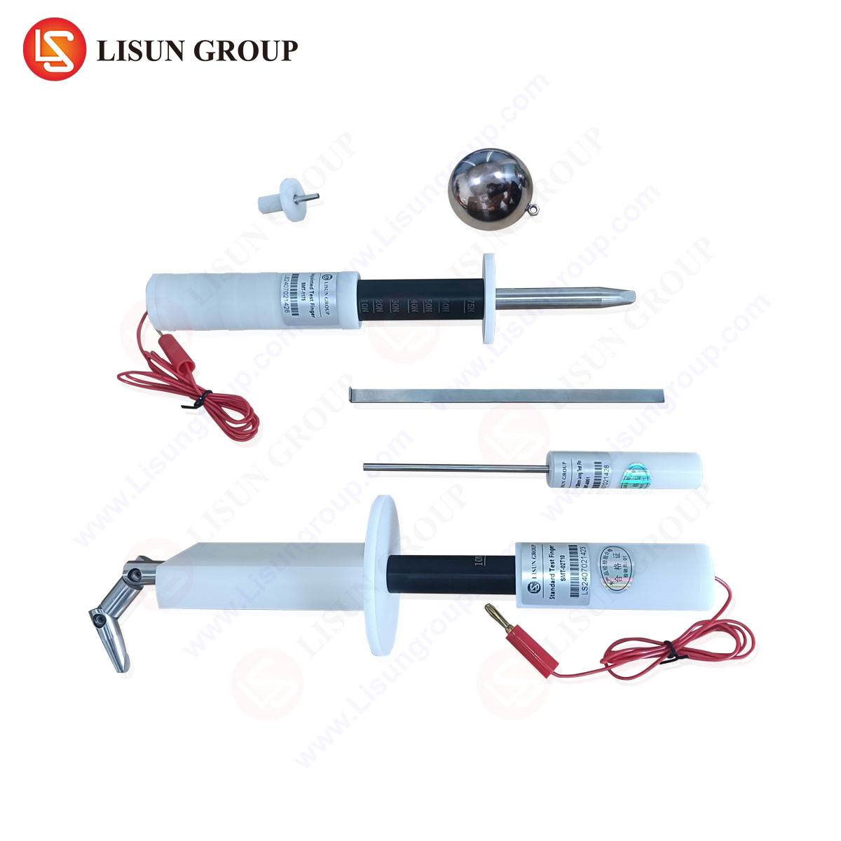
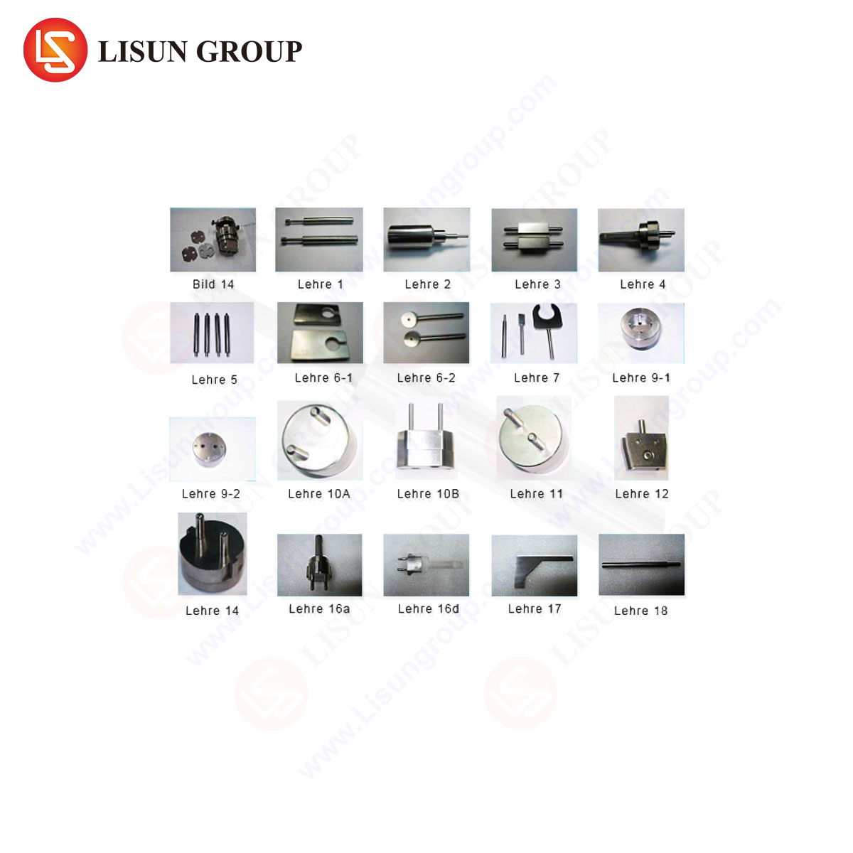
LISUN Gauges for Plugs and Sockets represent a calibrated, traceable solution for this fundamental compliance step. These gauge sets are machined to exacting tolerances from durable materials like tool steel or stainless steel, ensuring minimal wear over repeated use. A comprehensive set typically includes multiple “go” and “no-go” gauges for all critical features: pin diameter and span, entry apertures, shutter probe gauges, and checking gauges for recess requirements and pin bending tests.
The testing principle is rooted in physical metrology. For example, the LISUN LS-GA-001 series for BS 1363 sockets would include a “go” gauge that must fully enter the socket aperture with minimal friction, verifying the minimum size. Conversely, a “no-go” gauge must be prevented from entry, confirming the aperture is not oversized. Similarly, pin gauges verify that a plug’s live and neutral pins are not undersized (“go” gauge should fit) nor oversized (“no-go” gauge should not fit), ensuring correct contact pressure in a compliant receptacle. The competitive advantage of such dedicated systems lies in their standardization; they provide laboratories and manufacturers with a unambiguous, repeatable pass/fail criterion that aligns directly with the normative annexes of safety standards, eliminating subjective interpretation of dimensional drawings.
Industry Application Contexts for Plug and Socket Testing Regimes
The application of these tests spans the product lifecycle. Manufacturers employ them during R&D for prototype validation, during production for batch quality control, and for final product certification by National Certification Bodies (NCBs). For example, a producer of IEC 60320 appliance inlets must perform dimensional checks with C13/C14 gauges, dielectric tests, and temperature rise tests to secure a CB Scheme report. In the regulatory sphere, market surveillance authorities use identical gauge sets and test procedures to verify compliance of products already on the market, ensuring ongoing public safety.
Test houses and certification laboratories, such as those accredited to ISO/IEC 17025, rely on these methodologies as the bedrock of their safety assessments. The use of certified equipment like LISUN gauges is not merely best practice but often a mandatory requirement for accreditation, as it provides the necessary measurement traceability to national standards. Furthermore, large purchasers and specifiers, including government entities and multinational corporations, may reference these test protocols in their procurement contracts to ensure the reliability and safety of the electrical infrastructure they deploy.
Integrating Test Data into a Cohesive Safety Assessment
A singular test result is rarely conclusive. The power of the testing regimen lies in the integration of data from all domains—dimensional, mechanical, thermal, and electrical. A receptacle that passes dielectric testing might fail prematurely in endurance testing due to contact wear, which would subsequently be revealed in a post-endurance temperature rise test. Therefore, a complete type-test evaluation sequences these tests logically, often with the most destructive tests (like endurance) performed last on a sample set.
The final assessment is a holistic judgment. The device must demonstrate that its design, materials, and construction work in concert to meet all clauses of the applicable standard throughout its declared lifespan. This integrated approach ensures that a plug or socket is not merely dimensionally correct but is fundamentally safe under the electrical, thermal, and mechanical stresses of its intended use. The precision tools used at the start of this process, such as certified gauge sets, thus form the essential first link in a chain of evidence that culminates in a declaration of conformity and the affixation of a safety mark.
FAQ: Gauges and Testing for Plugs and Sockets
Q1: Why are “go/no-go” gauges preferred over digital calipers for plug and socket testing?
Digital calipers provide a variable measurement, requiring interpretation against tolerance limits. Certified “go/no-go” gauges offer a definitive, binary pass/fail outcome that aligns directly with the normative testing clauses in safety standards. This eliminates operator interpretation error, ensures repeatability between different labs, and is the method mandated by standards bodies for certification testing.
Q2: For a manufacturer producing plugs for multiple global markets, how many different gauge sets are typically required?
The number is significant, as each major standard (e.g., BS 1363, IEC Type G; AS/NZS 3112, IEC Type I; NF C 61-314, IEC Type E/F) has unique dimensional requirements. A manufacturer targeting ten different national markets may require ten distinct, certified gauge sets. Comprehensive systems, like those offered by LISUN, provide these as tailored kits for each standard, ensuring full compliance verification for each target geography.
Q3: Can a socket that passes initial dimensional tests still fail safety certification?
Absolutely. Dimensional conformance is a prerequisite but not a guarantee of overall safety. The socket must subsequently pass all other relevant tests, including dielectric strength, temperature rise, mechanical endurance, and tests for resistance to heat, arcing, and impact. A dimensionally correct socket could fail due to substandard insulating material, poor contact design leading to overheating, or a faulty shutter mechanism.
Q4: How often should a laboratory’s plug and socket gauges be recalibrated?
Recalibration intervals are dictated by the laboratory’s quality procedures, accreditation requirements (ISO/IEC 17025), and frequency of use. Typically, annual recalibration by an accredited metrology institute is standard practice. This ensures measurement traceability to national standards is maintained and that gauge wear has not pushed the tool outside its own permissible tolerances.
Q5: What is the significance of the shutter probe test in socket gauging?
The shutter probe test, specific to shutter-protected sockets (common in UK, EU, and other designs), verifies that the safety shutter mechanism functions correctly. A standardized probe simulates a foreign object (like a child’s finger) and must not be able to make contact with live parts. A dedicated gauge from a set will apply the precise force and geometry specified in the standard to test this protective feature objectively.