


A Technical Analysis of Attachment Plug Design, Verification, and the Imperative of Precision Gauging
Introduction: The Critical Interface in Electrical Connectivity
The attachment plug, a seemingly elementary component, constitutes a fundamental and safety-critical interface within global electrical infrastructure. Its primary function—to establish a secure, low-resistance electrical connection between a flexible cord and a fixed socket-outlet—belies the complex interplay of mechanical, electrical, and materials engineering required for its reliable operation. Failures within this interface range from benign connection loss to catastrophic events such as overheating, arcing, and fire initiation. Consequently, the design, manufacturing, and post-production verification of attachment plugs are governed by a stringent framework of international and national standards, including IEC 60884-1, BS 1363, AS/NZS 3112, and UL 498. This article provides a detailed examination of attachment plug design principles, the critical role of dimensional compliance, and the advanced methodologies employed for their verification, with a specific focus on the application of precision gauging systems such as the LISUN series for plugs and sockets.
Anatomical Deconstruction of a Standardized Attachment Plug
A comprehensive understanding of plug validation begins with an analysis of its constituent parts. A typical plug comprises a molded insulating body, conductive contact pins (line, neutral, and earth), internal terminations (screw, clamp, or solder), a cord grip, and, in many designs, a fuse. Each element must conform to exacting dimensional tolerances. The pins, for instance, are not simple cylinders; their geometry includes specific lengths, diameters, tip profiles (rounded or chamfered), and, crucially, their spatial relationship to one another—defined as pin span and pin setback. Deviations in pin diameter or coating thickness can lead to insufficient contact pressure within the socket, increasing contact resistance. Incorrect pin spacing or offset can prevent engagement or cause misalignment, potentially leading to partial insertion—a significant shock hazard. The insulating body’s dimensions, including the distance from pin tips to the face of the plug body (protrusion) and the profile of the shroud, are equally vital to ensure proper mating depth and user protection.
The Physics of Connection: Contact Resistance and Thermal Management
The electrical performance of a plug-socket pair is governed by the principle of contact resistance. At the microscopic level, even highly polished conductive surfaces make contact only at discrete asperities. The constriction of current flow through these limited points generates heat, described by Joule’s law (P = I²R). A well-designed plug minimizes this resistance through three mechanisms: sufficient contact normal force (provided by the socket’s contact springs), adequate conductive surface area, and the use of appropriate plating materials (e.g., tin, nickel, or silver) to mitigate oxidation. An undersized or misshapen pin reduces the effective contact area and may fail to properly deflect the socket springs, leading to a high-resistance connection. Under load, this connection will overheat, potentially degrading the plug and socket materials, accelerating oxidation, and creating a positive feedback loop of increasing resistance—a precursor to failure. Precision gauging indirectly validates this electrical performance by ensuring the mechanical prerequisites for a low-resistance interface are met.
Dimensional Tolerancing and the Framework of International Standards
Interoperability and safety are enforced through standards that specify absolute dimensional limits and “go/no-go” criteria. These are not arbitrary but are derived from extensive research into mating compatibility, mechanical strength, and electrical safety. For example, the earth pin is often longer to ensure protective earth connection is established before line contacts are energized. Standards define maximum and minimum limits for every critical dimension. A “go” gauge must fit freely, confirming a dimension is not too large (e.g., a pin is not overly thick). A “no-go” gauge must not fit, confirming a dimension is not too small (e.g., a pin is not undersized). This binary verification is the cornerstone of production line and quality assurance laboratory testing. The design and manufacture of these gauges themselves require metrological precision an order of magnitude greater than the components they test.
LISUN Gauges for Plugs and Sockets: A System for Comprehensive Verification
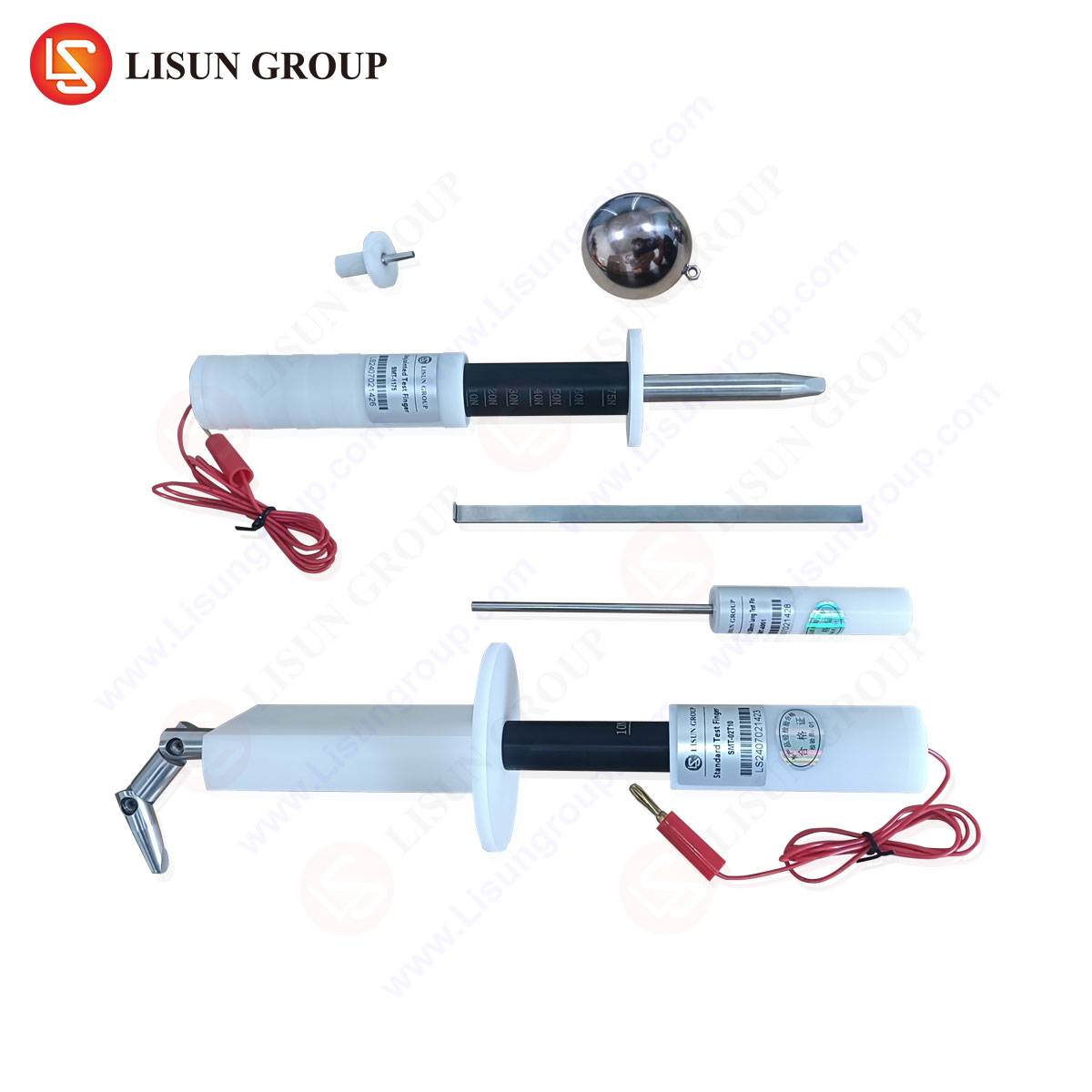
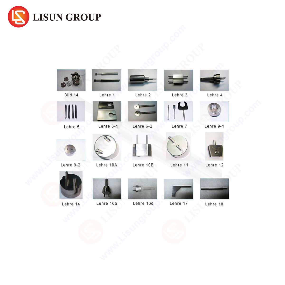
The LISUN series of gauges for plugs and sockets embodies a systematic approach to dimensional verification. This integrated system is engineered to provide a complete assessment of compliance for a wide array of global plug types (Types A, B, C, D, E, F, G, I, etc., as per IEC 60083). The system typically comprises modular gauge blocks, pin gauges, profile templates, and specialized fixtures designed to assess specific safety-critical features.
-
Specifications and Testing Principles: The gauges are manufactured from hardened tool steel or other dimensionally stable materials, with critical surfaces ground and lapped to tolerances within ±0.005 mm. Their operation is based on the definitive “go/no-go” principle. Key tests facilitated include:
- Pin Gauge Verification: Utilizing cylindrical “go” and “no-go” gauges to check the diameter of line, neutral, and earth pins.
- Pin Span and Setback: Employing precision gauge plates with slots or holes at the nominal and extreme allowable distances to verify the center-to-center spacing of pins and their offset from the plug face.
- Protrusion and Recess: Using depth steps or feeler gauges to measure the extension of pins beyond the plug shroud or their recess within it.
- Profile and Outline Checking: Template gauges to verify the external contour of the plug body, ensuring it does not encroach on zones reserved for socket-outlet surfaces and that it meets requirements for finger-safe design.
- Socket-Outlet Gauge Compatibility: Complementary gauges, such as the “test pin” and “checking gauge” specified in standards like BS 1363, are used to verify the contact geometry and entry apertures of socket-outlets, ensuring they will only accept compliant plugs.
-
Industry Use Cases: The primary application is within Quality Assurance (QA) laboratories of plug, socket, and cord-set manufacturers. It is used for First Article Inspection (FAI), routine production batch sampling, and failure analysis. Furthermore, third-party testing laboratories and certification bodies (e.g., UL, TÜV, Intertek) utilize such systems during type-testing for certification and during follow-up surveillance audits to maintain certificate validity. Import/export regulators may also employ them for market surveillance to prevent non-compliant products from entering the supply chain.
-
Competitive Advantages: The LISUN system’s value proposition lies in its comprehensiveness, traceability, and durability. A unified kit covering multiple standards reduces procurement complexity and calibration overhead. The gauges’ construction ensures long-term dimensional stability, resisting wear from repeated use. Their design strictly adheres to the letter of the referenced standards, providing unambiguous and defensible test results, which is critical in audit and certification contexts. This reduces subjectivity compared to less formal measurement methods.
The Consequence of Non-Compliance: A Risk-Based Assessment
Dimensional non-conformance in attachment plugs propagates risk through several failure modes. A plug with undersized pins may insert into a socket but will exhibit high contact resistance, leading to thermal overload. Conversely, oversized pins can cause permanent deformation of the socket contacts, degrading performance for all subsequent plugs used. Incorrect pin span can lead to forced insertion, damaging socket internals, or partial connection where live pins remain accessible—a severe electrocution risk. Non-compliant shrouding may fail to prevent finger contact with partially inserted pins. The use of precision gauging systems acts as a primary control point to intercept these non-conforming products before they enter commerce, directly mitigating electrical fire and shock hazards.
Integration of Gauging within a Broader Quality Management System
While essential, dimensional gauging is one node within a holistic product qualification regimen. A complete safety assessment includes:
- Electrical Testing: Dielectric strength (hipot), insulation resistance, and continuity.
- Mechanical Testing: Pin strength (bend test), impact resistance of the body, cord anchorage pull, and insertion/withdrawal force cycles.
- Thermal Testing: Temperature rise evaluation under rated current and abnormal overload conditions.
- Material Analysis: Flammability rating (e.g., UL 94 V-0) and tracking resistance of the insulating body.
Dimensional verification via gauges is the foundational first step; a plug that fails dimensional checks will invariably fail in subsequent performance tests. The data derived from gauging—particularly statistical process control (SPC) data tracking dimensional trends—can also inform manufacturing process adjustments, such as mold maintenance or pin plating bath management, moving quality control from detection to prevention.
Future Trajectories: Smart Manufacturing and Advanced Metrology
The evolution of plug verification is aligning with Industry 4.0 trends. While manual “go/no-go” gauging remains the standard for its simplicity and direct link to standards, automated optical measurement systems are increasingly used for high-speed, non-contact inspection on production lines, providing full 3D point-cloud data for statistical analysis. The role of systems like the LISUN gauges is evolving towards being the primary reference standard used to calibrate and validate these automated systems. In this paradigm, the physical gauge set serves as the unassailable reference artifact, ensuring the traceability and accuracy of high-volume automated inspection, thereby bridging traditional metrology with digital manufacturing.
Conclusion
The reliability of the ubiquitous attachment plug is predicated on rigorous adherence to dimensional specifications codified in international safety standards. Precision gauging is the indispensable methodology for enforcing this compliance. By providing a definitive, repeatable, and standards-based assessment of critical plug geometries, systems like the LISUN gauges for plugs and sockets perform a vital function in the manufacturing and quality assurance ecosystem. They serve as a fundamental technical barrier that prevents substandard products from compromising electrical safety, thereby underpinning the integrity of the global electrical connection interface.
FAQ Section
Q1: How frequently should a set of plug and socket gauges be calibrated?
Calibration intervals depend on usage frequency, material wear, and quality system requirements (e.g., ISO 9001). For active QA laboratories in a manufacturing environment, annual calibration by an accredited metrology lab is typical. Gauges used for critical certification testing may require verification prior to each test series. A regular visual inspection for damage or corrosion is also recommended.
Q2: Can one gauge set verify both plugs and sockets?
A comprehensive system, such as the LISUN series, typically includes separate, dedicated gauges for plugs and for sockets. The geometries tested are complementary but distinct. Plug gauges check pin dimensions and spacing. Socket gauges (like test pins and checking gauges) verify contact alignment, aperture size, and shutter operation. A complete compliance assessment requires both.
Q3: What is the significance of the “checking gauge” for socket-outlets?
The checking gauge is a specialized tool designed to verify several socket safety features simultaneously. It ensures that the shutter mechanism (where fitted) operates correctly, that the earth pin must be engaged first to open the shutters for the line/neutral pins, and that the socket apertures will not accept pins of incorrect cross-section or spacing. It is a composite functional test, not merely a dimensional one.
Q4: When performing a pin diameter check, what is the correct procedure if the “no-go” gauge slides onto the pin under its own weight?
If the “no-go” gauge fits over the pin using only its own weight (i.e., without any applied force), the pin is conclusively undersized and fails the test. The standard defines that the “no-go” gauge must not enter. This result indicates a non-conformity that could lead to high contact resistance and must trigger a rejection and investigation into the manufacturing process (e.g., plating thickness, pin machining).
Q5: How are gauges selected for a plug designed for a new market?
Selection is strictly driven by the national standard the plug is intended to meet. The first step is to identify the applicable standard (e.g., IS 1293 for India, GB 2099.1 for China). The gauge set is then specified based on the detailed dimensional requirements and test methods outlined in that standard’s sections for gauges. Manufacturers often maintain multiple gauge kits for the different regional markets they serve.