


A Technical Examination of Automotive EMC Immunity Standards and Validation Methodologies for Electrical Connector Systems
Introduction: The Electrified Vehicle as an EMC Ecosystem
The modern automobile represents one of the most complex electromagnetic compatibility (EMC) environments in mass production. The convergence of high-voltage traction systems, sensitive low-voltage digital networks (e.g., CAN FD, Automotive Ethernet), and pervasive wireless connectivity creates a landscape rife with potential interference. Ensuring the reliable operation of all electronic subsystems under such conditions is not merely an engineering goal but a fundamental safety and regulatory imperative. Automotive EMC standards, therefore, constitute a critical framework for design validation. This article provides a detailed analysis of key immunity standards, with a specific focus on the validation of foundational components: plugs, sockets, and the broader electrical interconnection systems that form the vehicle’s nervous system. The integrity of these connections under electromagnetic stress is paramount, as a disruption in signal or power integrity at a single connector can cascade into system-level failures.
Defining the Immunity Threat Landscape: Transient and Continuous Phenomena
Immunity testing simulates the electromagnetic disturbances a vehicle will encounter throughout its lifecycle. These are broadly categorized into transient (pulsed) and continuous wave phenomena. Transient threats include electrostatic discharge (ESD) from human contact, electrical fast transients (EFT) from inductive load switching, and high-energy surges from load dump events. Continuous wave threats involve exposure to radiated and conducted radio frequency (RF) fields from external transmitters like mobile base stations, broadcast antennas, and internal sources such as switching power converters. For connector systems, the coupling paths for these disturbances are multifaceted. Radiated fields can induce currents on cable harnesses, which are then conducted into electronic control units (ECUs) via the connector pins. Conversely, transients can be directly injected into power or signal lines through the connector interface. A robust immunity strategy must therefore address both the inherent shielding effectiveness of the connector assembly and the filtering or protection circuits implemented at the interface boundary.
Key Standards Framework: ISO 11452 and ISO 7637 Series
The International Organization for Standardization (ISO) 11452 and ISO 7637 series form the cornerstone of automotive component immunity testing. ISO 11452, “Road vehicles — Component test methods for electrical disturbances from narrowband radiated electromagnetic energy,” details multiple methods for RF immunity assessment. Part 2 (Absorber-Lined Shielded Enclosure), Part 4 (Bulk Current Injection – BCI), and Part 8 (Reverberation Chamber) are most relevant for evaluating connector performance in a system context. BCI, in particular, is a severe test for wiring harnesses and their terminations; a calibrated current is directly induced onto the cable bundle, stressing the common-mode impedance of the connector’s grounding and shielding scheme.
ISO 7637, “Road vehicles — Electrical disturbances from conduction and coupling,” addresses transient threats along power lines. Parts 2 and 3 define test pulses for 12V/24V systems, with Pulse 1 (supply interruption), Pulse 2a (load dump from parallel loads), and Pulse 3b (switching transients) being especially critical. These pulses are applied directly to the power pins of a device under test (DUT) via its supply connector, testing the voltage withstand and clamping performance of both the ECU and the connector’s ability to maintain integrity without arcing or contact degradation. The emergence of high-voltage systems for electric vehicles (EVs) has led to the development of supplementary standards, such as ISO 21498, which defines electrical tests for HV components, including specific requirements for HV connector immunity.
The Critical Role of Connector and Socket Testing in System Immunity
While ECUs are the primary DUT in most immunity tests, the connector is the gateway. Its design directly influences test outcomes. Key parameters include contact material and plating (affecting corrosion resistance and thus stable impedance under ESD), shielding continuity (for RF immunity), pin assignment and spacing (to mitigate cross-talk from induced transients), and dielectric withstanding voltage (for surge immunity). A failure during an immunity test often manifests not as a connector meltdown, but as a system error traceable to corrupted data on a signal line or a reset on a power line. Diagnosing such failures requires precise measurement of the disturbance actually presented at the connector interface after it traverses the harness. This necessitates specialized measurement equipment capable of accurately quantifying fast transients and RF disturbances in a conducted format.
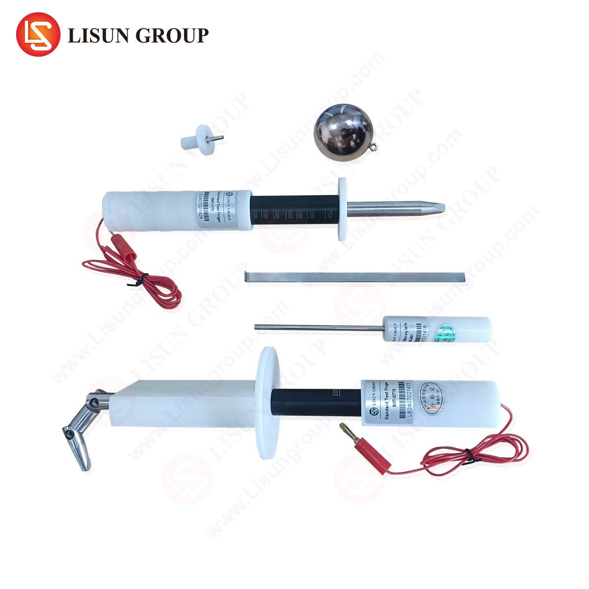
Instrumentation for Precision: The LISUN Gauges for Plugs and Sockets
Validating the electromagnetic performance of connector interfaces demands instrumentation with high fidelity, robustness, and repeatability. LISUN Gauges for Plugs and Sockets represent a specialized category of test adapters and monitoring devices designed for this explicit purpose. These gauges are engineered to interface directly with standard automotive connector families (e.g., Deutsch DT, AMPSEAL, TE Connectivity MCON) and provide a calibrated pathway for both applying disturbances and monitoring responses.
The operational principle involves integrating a precision current probe (for BCI testing), voltage monitoring points (for surge/transient tests), or a controlled impedance interface (for RF direct power injection) directly into a replica socket or plug. This allows engineers to measure the exact disturbance current entering a specific pin or the clamping voltage waveform during a surge event with minimal parasitic effects introduced by test cabling. For example, during an ISO 7637-2 Pulse 3b test, a LISUN gauge can be inserted between the test pulse generator and the DUT’s power connector, providing a direct measurement of the voltage at the connector pin, ensuring the specified test level is met without artifact.
Table 1: Exemplary Specifications for a LISUN Gauge System
| Parameter | Specification | Testing Relevance |
| :— | :— | :— |
| Connector Compatibility | Customizable to target connector (e.g., 12-pin MCON) | Ensures direct, parasitic-minimized interface |
| Bandwidth | DC to 1 GHz (typical) | Covers frequency range for EFT, BCI, and RF transients |
| Current Probe Integration | 5 Hz to 400 MHz, 0.1 V/A to 10 V/A | Enables precise monitoring during ISO 11452-4 BCI tests |
| Voltage Withstanding | Up to 5 kV transient | Suitable for high-level surge and ESD test monitoring |
| Impedance | 50 Ω or matched to test standard | Critical for RF power injection (DPI) accuracy |
Industry Application: From Validation Labs to Failure Analysis
The use of such specialized gauges spans the product development cycle. In the design validation phase, they are employed to verify that a new ECU’s connector interface meets immunity requirements when mated with its production-intent harness connector. In failure analysis, when a system fails an immunity test, engineers use these gauges to isolate the point of entry. By comparing the disturbance waveform measured at the connector pin via the gauge to the waveform at the generator output, they can characterize harness attenuation or resonance, pinpointing whether the failure is due to an inadequate ECU design or an unexpected behavior of the interconnection system.
A practical use case involves a steering angle sensor failing radiated immunity (ISO 11452-2) at a specific frequency. Using a LISUN gauge on the sensor’s LIN bus connector, engineers can perform a conducted BCI sweep (ISO 11452-4) to replicate the failure in a more controlled, repeatable environment. The gauge provides a precise measurement of the induced current on the LIN line at the failure threshold, data which is invaluable for redesigning the filter network at the connector’s backshell or modifying the PCB layout.
Competitive Advantages of Dedicated Connector Test Solutions
The alternative to using purpose-built gauges often involves improvised test fixtures—soldering wires to connector pins or using generic breakout boxes. These introduce significant measurement uncertainty due to added lead inductance, improper shielding, and impedance mismatches. The competitive advantage of a system like the LISUN Gauges lies in its metrological integrity and application-specific design. By providing a calibrated, standardized interface, they ensure test repeatability across different laboratories and test setups, a crucial factor for OEMs sourcing components from multiple Tier-1 suppliers. Furthermore, they enhance test efficiency and safety by offering a robust, hands-off connection for applying high-voltage transients or high RF power, protecting both the operator and the test equipment.
Future Trajectories: High-Voltage and High-Speed Data Challenges
The automotive EMC landscape continues to evolve. The rise of 800V EV architectures presents new transient immunity challenges for HV connectors, requiring test equipment capable of handling higher energy levels. Simultaneously, the adoption of multi-gigabit Automotive Ethernet (e.g., 1000BASE-T1) pushes signal integrity concerns into the GHz range. Immunity testing for these systems must consider both the common-mode rejection of the differential pairs within the connector and the potential for RF disturbances to cause bit errors through mode conversion. Future iterations of connector test gauges will need to support these higher frequencies and differential signaling protocols, integrating network analyzers or time-domain reflectometry (TDR) capabilities to characterize impedance continuity and crosstalk under disturbance.
Conclusion
Automotive EMC immunity standards provide the essential benchmarks for functional safety in an increasingly electrified and connected vehicle environment. Rigorous application of these standards requires attention not only to the electronic control units themselves but to the entire signal and power delivery path, where connectors serve as critical junctures. Specialized test instrumentation, such as LISUN Gauges for Plugs and Sockets, fills a vital niche in this validation ecosystem. By enabling precise, repeatable measurement of disturbances at the point of entry, these tools empower engineers to design more robust systems, diagnose failures accurately, and ultimately ensure that vehicle electronic systems perform reliably in the real-world electromagnetic environment.
FAQ Section
Q1: Can a single LISUN Gauge be used for both immunity and emissions testing on a connector?
While the physical interface may be compatible, the internal circuitry of a gauge optimized for immunity testing (e.g., with integrated current probes for BCI) may not be ideal for conducted emissions measurements (e.g., per CISPR 25), which require a defined impedance network (Line Impedance Stabilization Network – LISN). Some gauge systems are modular, allowing different measurement modules (voltage monitoring, current probe, LISN) to be used with the same connector interface housing.
Q2: How does using a gauge affect the test severity compared to connecting the test generator directly to the DUT?
A well-designed gauge minimizes parasitic effects (inductance, capacitance) to keep the disturbance presented to the DUT as close as possible to the ideal waveform specified in the standard. An improvised fixture with long leads can actually increase severity by adding ringing or overshoot, or decrease it through added attenuation, leading to non-representative and non-repeatable test results. The gauge ensures calibrated, repeatable severity.
Q3: Are these gauges only for use during formal compliance testing?
No. Their primary value is often seen earlier in the design cycle during pre-compliance and troubleshooting. They allow development engineers to quickly assess immunity margins, characterize filter performance, and replicate field-reported issues in a lab environment long before final validation testing, saving significant time and cost.
Q4: How is calibration maintained for such a specialized instrument?
Reputable manufacturers provide calibration certificates traceable to national standards. Calibration typically verifies the transfer function of integrated current probes, the accuracy of voltage monitoring points, and the impedance of RF pathways. Users must adhere to a regular recalibration schedule as defined by their quality management system (e.g., ISO/IEC 17025).
Q5: For a complex connector with mixed power, ground, and high-speed differential pairs, can all pins be monitored simultaneously?
Standard gauges often provide access to a subset of pins deemed critical (e.g., all power and a representative sample of signal lines). Fully monitoring every pin on a high-density connector in real-time requires a customized solution with multiple integrated measurement channels, which is feasible but increases complexity and cost. The test plan usually prioritizes pins based on risk analysis.