


Advancements in Electrostatic Discharge Simulation for Automotive Component Validation
The relentless electrification and digitalization of the automotive industry have precipitated a paradigm shift in electromagnetic compatibility (EMC) requirements. Within this complex landscape, Electrostatic Discharge (ESD) represents a persistent and formidable threat to vehicle electronic control units (ECUs), sensor arrays, and infotainment systems. The transient nature of ESD events, characterized by sub-nanosecond rise times and currents exceeding 30 amperes, can induce latent damage, soft errors, or catastrophic failure in semiconductor components. Consequently, rigorous and standardized ESD testing has transitioned from a recommended practice to a non-negotiable pillar of automotive component qualification. This article delineates the technical architecture of modern automotive ESD simulator solutions, with a focused examination on critical calibration and verification tools, such as target fixtures for plugs and sockets.
The Evolution of Automotive ESD Standards and Test Methodologies
Contemporary automotive ESD testing is governed by a stringent framework of international standards, primarily the ISO 10605 and the OEM-specific adaptations of IEC 61000-4-2. These documents prescribe not only the waveform parameters—such as the 150pF/330Ω model for simulating human-body metal discharge or the 330pF/2kΩ model for human-body discharge through air—but also the entire test ecosystem. This includes the ESD generator, the coupling plane, the direct and indirect application methods, and the Device Under Test (DUT) setup. A critical, yet often under-specified, element within this ecosystem is the interface between the simulator’s discharge tip and the physical port of the DUT. For components featuring plugs, sockets, or other connector-based interfaces, ensuring a consistent, low-inductance, and repeatable discharge path is paramount. Inconsistencies in this interface can lead to waveform distortion, arcing variability, and ultimately, non-reproducible test results that compromise the validity of the entire qualification campaign.
Architectural Components of a Modern ESD Simulator System
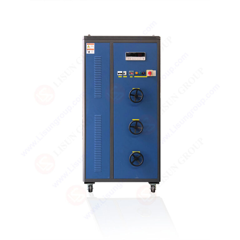
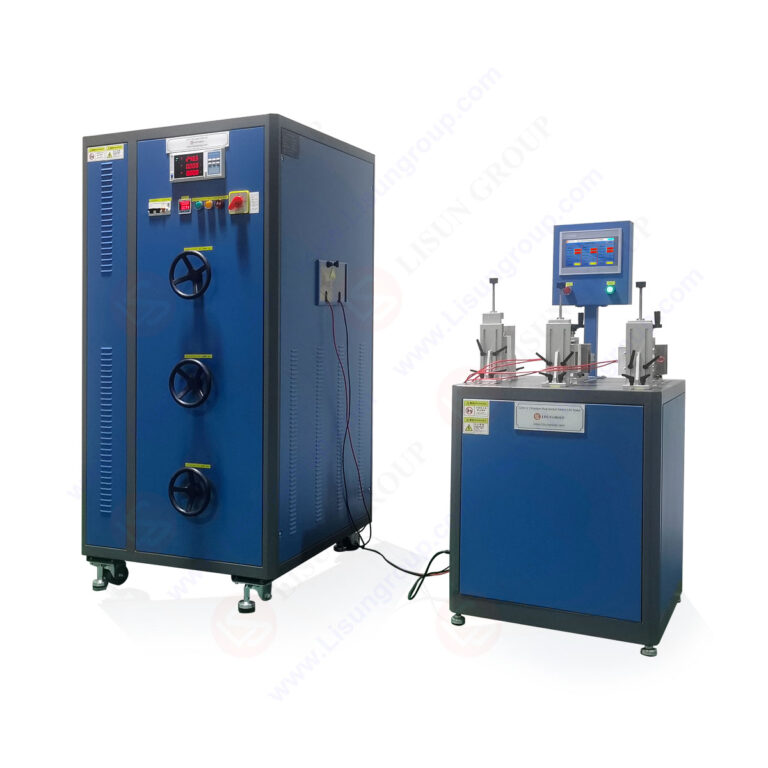
A state-of-the-art automotive ESD simulator is a sophisticated instrument comprising several synchronized subsystems. The high-voltage DC supply charges a storage capacitor to a predefined voltage level, typically ranging from 2 kV to 30 kV for automotive applications. A high-speed, low-bounce relay then discharges this capacitor through a network of resistors into the discharge tip. The fidelity of the generated current waveform, particularly its rise time and peak amplitude, is the primary metric of simulator performance. However, the system’s utility is contingent upon ancillary components: the ground reference plane, the horizontal and vertical coupling planes for indirect testing, and a suite of specialized discharge tips and target fixtures. It is within this last category that precision engineering becomes most evident, especially for testing connectorized automotive components like charging inlets, data link connectors (e.g., OBD-II ports), or coaxial antenna sockets.
Precision Target Fixtures: The Critical Interface for Connector Testing
When testing a component with a socket, such as a USB port or a power charging receptacle, applying the discharge directly to a pin within that socket presents a mechanical challenge. A handheld discharge tip cannot guarantee a stable, perpendicular, and low-inductance connection. This is where dedicated target fixtures, or gauges, become indispensable. These devices are engineered to mate precisely with the DUT’s socket, presenting a defined, flat target surface to which the ESD simulator’s discharge tip can be applied in a consistent manner. The fixture itself is constructed from conductive material and is bonded directly to the ground reference plane, ensuring the discharge current follows the prescribed path as outlined in the standard. The geometric design, material conductivity, and grounding impedance of these fixtures are non-trivial engineering considerations that directly influence the injected current waveform.
Introducing the LISUN Gauges for Plugs and Sockets: A Technical Analysis
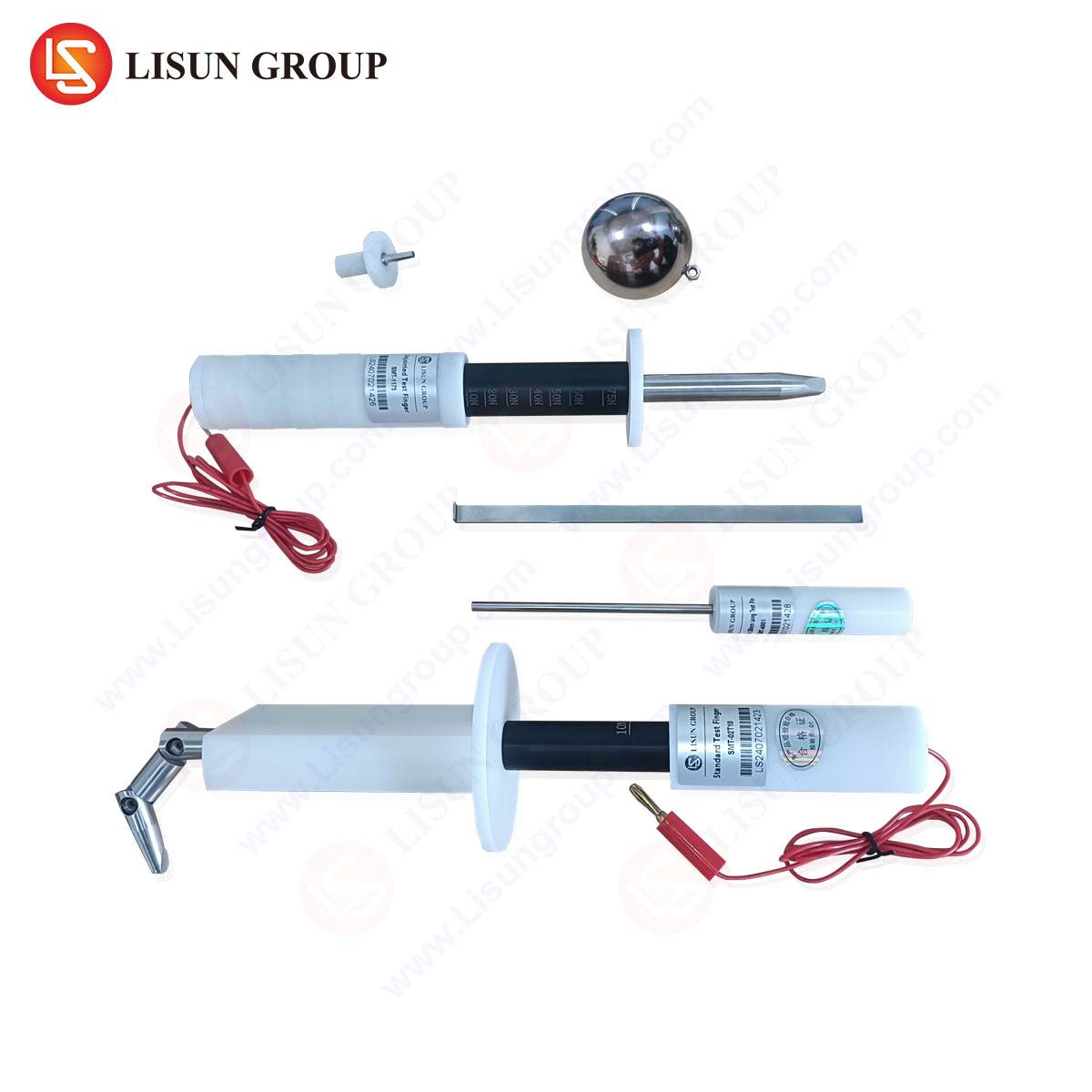
To address the precise requirements of connectorized component testing, specialized tools such as the LISUN Gauges for Plugs and Sockets have been developed. These gauges are not generic adapters but are calibrated instruments designed to fulfill the specific mounting and discharge application requirements of standards like ISO 10605 and IEC 61000-4-2 for socket-based interfaces.
The operational principle is grounded in providing a standardized and repeatable discharge target. The gauge is inserted into the DUT’s socket, replicating the mating action of a genuine plug. Its body establishes a direct electrical connection to the relevant pins of the socket (e.g., the ground pin or the signal pin under test). A dedicated target plate, typically a flat circular or square surface of specified dimensions, is then presented externally. This plate serves as the unambiguous point of contact for the ESD simulator’s discharge tip. By eliminating the variable of hand-applied probe positioning inside a recessed socket, the gauge ensures that for every test shot, the discharge path’s inductance and resistance are constant, leading to highly reproducible current injection.
Specifications and Design Considerations:
A typical gauge system includes a set of fixtures tailored for common automotive connectors (e.g., USCAR, FAKRA, MQS, or custom OEM sockets). Key specifications include:
- Target Plate Dimensions: Precisely machined to meet the contact requirements specified in applicable standards (e.g., a 20mm diameter circle is common).
- Contact Resistance: Minimized to <10 mΩ between the target plate and the gauge’s mating pins to prevent unwanted voltage drops.
- Material: High-conductivity, corrosion-resistant alloys such as brass with gold or nickel plating to ensure stable performance over thousands of discharge cycles.
- Dielectric Withstand: The insulating portions of the gauge must withstand the high-voltage fields present during air-discharge testing without flashover.
- Mechanical Tolerance: Pins and housing are manufactured to tight tolerances to ensure a secure, wobble-free fit in the corresponding socket, mimicking a real connector’s engagement.
Industry Application in Plug and Socket Component Validation
The use case for these gauges spans multiple automotive component categories. In the domain of electric vehicle (EV) power systems, the charging inlet (e.g., a Type 1 or Type 2 socket) must be tested for ESD immunity. A gauge designed for this socket allows test engineers to apply discharges directly to the pilot control pin or the protective earth pin in a controlled fashion. For in-vehicle networking, the ubiquitous OBD-II diagnostic port is a frequent entry point for ESD transients; a corresponding gauge enables systematic testing of each pin in the 16-pin connector. Similarly, infotainment systems with USB-A, USB-C, or HDMI ports require precise discharge application to the data lines, which is only achievable with a purpose-built target fixture. Beyond consumer ports, sensor connectors (e.g., for LiDAR, radar, or camera modules) also necessitate this level of testing precision to ensure reliability in harsh automotive environments.
Comparative Advantages in Testing Reproducibility and Standard Compliance
The competitive advantage of employing calibrated target gauges like the LISUN series manifests in several critical areas. Primarily, they eliminate operator-dependent variability. Manual probing into a socket is inherently inconsistent, affecting the discharge waveform’s rise time and peak current. Secondly, they enhance test repeatability and reproducibility (R&R), a core tenet of any quality assurance process. Data collected using a gauge across different labs or different days is inherently more comparable. Thirdly, they protect the DUT and test equipment. A slip of a handheld probe can short adjacent pins on a dense socket, causing collateral damage. A gauge prevents this by isolating the discharge path. Finally, they ensure unambiguous standard compliance. Many automotive OEM test specifications explicitly require the use of a “test fixture” or “target adapter” for connector testing. Using a gauge designed for this purpose provides documented evidence of correct test setup.
Integrating Target Fixtures into a Comprehensive ESD Test Regimen
Deploying these gauges effectively requires integration into a holistic test plan. The process typically involves:
- Selection: Choosing the gauge that corresponds exactly to the DUT’s socket type and the specific pin under test.
- Mounting: Securely inserting the gauge into the DUT’s socket, which is itself mounted on an insulating support over the ground reference plane.
- Connection: Ensuring the gauge’s grounding strap or body is bonded with low inductance to the ground plane.
- Calibration Verification: Periodically verifying the entire test setup, including the gauge, by using a current target and a wide-bandwidth current probe to confirm the injected waveform meets the requirements of ISO 10605 at the point of injection.
Data Integrity and the Role of Calibrated Accessories
The importance of calibrated accessories in the measurement chain cannot be overstated. While the ESD simulator itself undergoes annual calibration, the degradation or imperfection of a target fixture can introduce systematic errors. A worn or oxidized contact pin on a gauge can add series resistance, attenuating the peak current. Therefore, treating these fixtures as calibrated instruments—with periodic verification of their contact resistance and mechanical integrity—is a best practice that safeguards the validity of test data. This is especially crucial in automotive applications where component lifetimes are measured in decades and failure rates must be in the single-digit parts per million.
Conclusion
As automotive electronics continue to increase in density and sensitivity, the methodologies for validating their robustness must evolve with commensurate precision. ESD testing, a cornerstone of electrical robustness validation, demands attention to every element of the test chain. The utilization of engineered target fixtures for plugs and sockets, such as the LISUN Gauges, represents a significant advancement in achieving the necessary levels of repeatability, standardization, and data integrity. By transforming a variable mechanical interface into a controlled electrical one, these tools enable engineers to generate reliable, actionable data, ultimately contributing to the enhanced reliability and safety of modern vehicles.
FAQ Section
Q1: Why can’t I simply use a standard discharge tip directly on the pins inside a socket?
A: Applying a handheld discharge tip inside a recessed socket introduces multiple variables: inconsistent contact pressure, angular alignment, and point of contact. This alters the parasitic inductance of the discharge path, which directly modifies the rise time and amplitude of the injected current waveform, leading to non-repeatable and potentially non-compliant test results.
Q2: How do I select the correct gauge for a specific automotive connector?
A: Selection is based on the connector’s formal specification (e.g., USCAR-30, FAKRA). The gauge must be the mating counterpart to the DUT’s socket. Manufacturers provide gauges for common standards. For proprietary OEM connectors, a custom gauge may need to be engineered based on the connector’s mechanical drawings and pinout.
Q3: Are these target fixtures required by ISO 10605 or IEC 61000-4-2?
A: While the base standards describe the principle of direct application to “terminals and connectors,” many derivative automotive OEM test specifications explicitly mandate the use of a dedicated test fixture or adapter for any connectorized port to ensure standardization. Using such a fixture is considered a best practice for demonstrating compliance with the standard’s intent.
Q4: How often should a target gauge be verified or calibrated?
A: As a critical part of the test setup, it is recommended to verify the gauge’s key parameters, such as contact resistance and mechanical integrity, at intervals aligned with your lab’s quality schedule, typically every 6 to 12 months. This can be part of an internal check using a milliohm meter and visual inspection for wear or damage.
Q5: Can a single gauge be used for both contact discharge and air discharge testing on a socket?
A: Yes, a properly designed gauge serves as the target for both modes. In contact discharge, the simulator’s tip is in physical contact with the gauge’s target plate before discharge. In air discharge, the charged tip is moved toward the same target plate until a spark occurs. The gauge ensures the spark always originates from a consistent distance and geometry relative to the DUT’s internal circuitry.