


Advancements in Electrostatic Discharge Immunity Testing for Automotive Plugs and Sockets
Introduction: The Criticality of ESD Robustness in Modern Vehicle Architectures
The automotive industry’s relentless progression towards electrification, connectivity, and autonomous functionality has precipitated a profound transformation in vehicle electronic architecture. Contemporary vehicles now incorporate a dense network of Electronic Control Units (ECUs), high-speed data buses, and sensitive sensor arrays, all interconnected via an extensive and complex harness system. Within this ecosystem, plugs and sockets serve as critical nodal points, facilitating both power distribution and high-integrity data transmission. Consequently, the electrostatic discharge (ESD) immunity of these connector systems has evolved from a secondary consideration to a paramount design and validation criterion. An ESD event, a transient transfer of charge between bodies at different electrostatic potentials, can induce catastrophic failure or latent damage in semiconductor components, leading to system malfunctions that compromise vehicle safety, reliability, and functionality. This article delineates the methodologies, standards, and specialized instrumentation required for comprehensive ESD immunity testing of automotive plugs and sockets, with a particular focus on integrated testing solutions.
Fundamental ESD Phenomena and Their Impact on Connector Systems
Electrostatic discharge manifests in two primary forms relevant to automotive environments: air discharge and contact discharge. Air discharge simulates a spark jumping from a charged human body or tool to a device as an approach is made. Contact discharge, often considered more reproducible for testing, involves bringing the charged generator tip into direct contact with the Unit Under Test (UUT) prior to discharge initiation. For plugs and sockets, the vulnerability points are multifarious. Discharge can be injected directly onto connector pins housing signal or power lines, coupling energy directly into the circuitry. Perhaps more insidiously, ESD can occur on the connector housing or adjacent shielded cables, where the resulting high-frequency electromagnetic field can capacitively or inductively couple onto internal conductors, inducing transient voltages and currents on supposedly protected lines.
The failure modes are equally diverse. Hard failures include dielectric breakdown within insulation materials, vaporization of metallic contacts, or destruction of integrated circuits. Soft errors, such as bit flips in memory, temporary latch-up states, or software glitches, are increasingly problematic as they can cause intermittent and difficult-to-diagnose system resets or erroneous sensor readings. For power connectors in electric vehicle (EV) charging ports or battery management systems, an ESD event could potentially disrupt critical safety functions. Therefore, testing must not only verify survival but also ensure uninterrupted operational performance during and after the transient event.
Evolution of Automotive ESD Standards: ISO 10605 and OEM-Specific Requirements
The cornerstone standard for automotive ESD testing is ISO 10605:2008, “Road vehicles — Test methods for electrical disturbances from electrostatic discharge.” This standard defines test procedures, test levels, and environmental conditioning (humidity) requirements. It specifies distinct test levels for both contact and air discharge, with voltages ranging from ±2 kV for low-level sensitivity components up to ±25 kV or higher for components likely to experience direct human contact, such as infotainment panels or charging connectors.
However, ISO 10605 provides a foundational framework; most global Original Equipment Manufacturers (OEMs) and Tier-1 suppliers impose more stringent, proprietary test specifications. These corporate standards often mandate higher test voltages, additional test points (including indirect discharges to coupling planes near the harness), and specific performance criteria during testing (e.g., Performance Criteria A: no degradation or loss of function). Testing is typically performed under both “human body model” (HBM) and, increasingly, under the more severe “charged device model” (CDM) conditions, the latter simulating the rapid discharge from a charged component itself. The test regimen for a plug or socket assembly is not performed in isolation but as part of a subsystem or module, with discharges applied to the connector housing, individual pins, and adjacent wiring loom.
Integrated Test Solutions: The Role of Specialized ESD Simulators and Fixturing
Effective ESD immunity testing requires a calibrated, programmable ESD simulator capable of generating highly repeatable discharges per IEC 61000-4-2 and ISO 10605 waveforms. The key waveform parameters—rise time (0.7–1 ns for contact discharge), peak current, and current derivatives (di/dt)—must be rigorously verified, as these factors determine the spectral content and coupling efficiency of the pulse. Modern simulators offer sophisticated sequencing, allowing for automated sweeps of test voltages (e.g., from ±4 kV to ±15 kV) and polarities at multiple test points.
The critical challenge for connector testing lies in the fixturing and application of the discharge. Applying the discharge tip directly to a miniature connector pin is mechanically challenging and risks damaging the pin. Therefore, dedicated test fixtures and application tools are essential. These fixtures must securely hold the connector mated pair or the socket integrated into its module, while providing precise, repeatable access for the ESD gun tip to defined test points. For indirect testing, a horizontal coupling plane (HCP) or vertical coupling plane (VCP) is positioned beneath or beside the wiring harness, and discharges are applied to the plane, testing the coupling immunity of the connector and its attached circuitry.
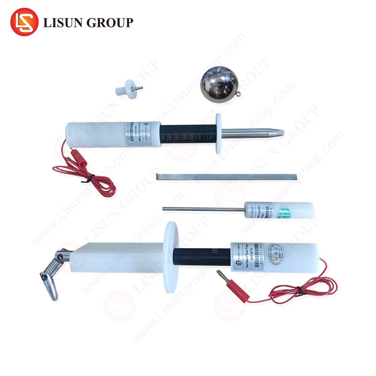
Characterizing Connector Performance with Precision Measurement: The LISUN Gauges for Plugs and Sockets
A pivotal component in a robust ESD test regimen for connectors is the precise measurement of the discharge current waveform at the point of injection. This is where specialized measurement instruments, such as the LISUN Gauges for Plugs and Sockets, become indispensable. These devices are not passive adapters but calibrated measurement transducers designed to be integrated directly into the test setup between the ESD simulator and the connector under test.
The operating principle is based on a current shunt or current transformer integrated within a form factor that mimics a standard connector housing or incorporates a test probe interface. When an ESD pulse is injected through the gauge, it provides a calibrated, low-inductance path while simultaneously generating a proportional voltage output that is fed to a high-bandwidth oscilloscope (typically ≥2 GHz bandwidth). This allows for real-time verification that the actual current waveform injected into the specific pin or housing of the connector complies with the required standard (e.g., the ISO 10605 waveform). Key measured parameters include the initial peak current (I_peak at 30 ns), the current at 60 ns (I_60), and the rise time.
Table 1: Example Specifications for a High-Fidelity Connector ESD Measurement Gauge
| Parameter | Specification | Importance |
| :— | :— | :— |
| Bandwidth | DC to >1 GHz | Accurately captures sub-nanosecond rise times of ESD pulses. |
| Rise Time | <350 ps | Ensures minimal distortion of the measured pulse waveform. |
| Dynamic Range | Up to 30 A peak | Covers the full range of automotive ESD test levels (e.g., ±2kV to ±25kV into 2Ω). |
| Calibration | Traceable to NIST or equivalent | Guarantees measurement accuracy and compliance with quality management systems (IATF 16949). |
| Form Factor | Customizable for target connector series (e.g., USCAR, Deutsch, AMP) | Enables direct, repeatable insertion into the test circuit without ad-hoc modifications. |
Application in Industry Use Cases: From Validation to Failure Analysis
The deployment of such measurement gauges spans the product development lifecycle. During the Design Validation (DV) phase, engineers use them to establish a baseline of ESD performance for a new connector design, comparing different shielding effectiveness, contact geometries, or insulating materials. By measuring the actual current entering the pin, they can correlate specific waveform characteristics with observed failures, moving beyond simple pass/fail results to parametric analysis.
In Failure Analysis and root-cause investigation, these tools are critical. If a connector assembly fails a system-level ESD test, the gauge can be inserted to determine if the failure is due to an anomalous test pulse (e.g., from simulator drift or improper grounding) or a genuine weakness in the device. It allows for the differentiation between a “test issue” and a “design issue.” Furthermore, for testing charging inlet connectors for electric vehicles (e.g., CCS, CHAdeMO), which are large and exposed, verifying the ESD pulse integrity at the exact contact point is essential for certifying the safety and reliability of the high-voltage system.
Competitive Advantages of Direct-Injection Measurement Methodology
The integration of a dedicated measurement gauge like the LISUN system offers several distinct advantages over indirect verification methods. Primarily, it provides measurement certainty. Verifying the simulator output into a 2-ohm validation target is standard practice, but it does not guarantee the same waveform is delivered to the actual, complex impedance of a connector pin. The gauge confirms the in-situ pulse.
Secondly, it enhances test repeatability and reproducibility (R&R). By eliminating variability from hand-held gun application angle, pressure, and approach speed, and instead using a fixture-integrated gauge, test results become consistent across different labs and technicians. This is a crucial factor in supplier-OEM validation processes.
Finally, it enables advanced diagnostics. By analyzing the subtle reflections and distortions in the measured current waveform, experienced engineers can infer characteristics about the connector’s impedance, the presence of parasitic capacitances, or the onset of arc-over phenomena within the connector body, providing invaluable feedback for design iteration.
System-Level Test Integration and Best Practices
A complete ESD test solution for automotive plugs and sockets integrates multiple components: the ESD simulator, the measurement gauge/fixture, a grounded reference plane, the Device Under Test (DUT) in its operational state (powered and communicating), and monitoring equipment to assess functional performance. The DUT should be exercised according to its worst-case operational profile during testing. For a socket connected to a CAN transceiver, this might involve continuous error-frame monitoring. For a power connector, voltage and current ripple should be monitored.
Best practices dictate testing under multiple environmental conditions, particularly low relative humidity (e.g., 20%–30%), as specified in ISO 10605, which promotes higher electrostatic potentials. Pre-test conditioning, including cleaning of connector surfaces to remove temporary anti-static coatings, is vital. A comprehensive test plan will define a matrix covering all feasible discharge points (each pin, housing corners, cable shield drain wires) with both polarities and multiple discharge counts per point.
Conclusion: Ensuring Reliability in an Electrified Future
As vehicle architectures continue to increase in complexity and criticality, the role of the humble plug and socket as a potential ESD vulnerability vector demands rigorous attention. A scientifically grounded testing methodology, anchored by precise waveform verification at the point of injection, is no longer a luxury but a necessity for achieving the “zero-defect” quality targets of the automotive industry. By employing integrated test solutions that combine standardized discharge generation with connector-specific measurement instrumentation, engineers can transition from qualitative pass/fail assessments to quantitative, data-driven design optimization. This approach not only mitigates field failure risks but also accelerates development cycles by providing clear, actionable insights into the electromagnetic robustness of one of the vehicle’s most fundamental electrical components.
FAQ Section
Q1: Why is it necessary to measure the ESD pulse directly at the connector pin when the simulator is already calibrated?
A: Calibration verifies the simulator’s output into a defined, resistive load (typically 2 ohms). The actual impedance presented by a connector pin, its attached PCB trace, and the integrated circuit is complex and reactive. This impedance mismatch can alter the delivered current waveform. Direct measurement confirms the stress actually imposed on the device, ensuring test validity.
Q2: Can the LISUN Gauges be used for testing according to both ISO 10605 and IEC 61000-4-2?
A: Yes, the core measurement principle is applicable to both standards. The key difference lies in the test setup and discharge network (RC values). The gauge measures the actual current waveform injected; whether that waveform’s parameters align with ISO or IEC requirements is determined by the simulator’s settings and the verification of the measured trace against the relevant standard’s waveform template.
Q3: How are these measurement gauges integrated into automated test sequences?
A: The gauge’s output is a analog voltage signal proportional to the discharge current. This signal is connected to a high-speed oscilloscope. Using instrument control software (e.g., via GPIB, LAN, or USB), the test sequence can be programmed to trigger the scope upon discharge, capture the waveform, and automatically analyze key parameters (peak current, rise time) against pre-set limits, logging the results for each test point.
Q4: Are custom gauge form factors available for proprietary or less common connector types?
A: Yes, leading providers typically offer customization services. Given the vast array of connector series used in automotive applications (from miniature FAKRA to high-voltage EV connectors), the ability to design a gauge interface that mates securely with the specific connector under test is essential for accurate and repeatable measurements. This often involves collaborative design between the test equipment supplier and the automotive engineer.
Q5: Does using a measurement gauge affect the severity of the ESD test applied to the device?
A: A well-designed gauge is engineered to have minimal impact. Its insertion inductance and resistance are characterized and kept extremely low to avoid significantly altering the discharge path compared to a direct connection. The primary purpose is measurement, not attenuation. Its specifications, particularly rise time and bandwidth, are selected to ensure it does not filter or distort the critical high-frequency components of the ESD pulse.