


An Analysis of BS 1363-2 Socket Contact Design and Verification Methodologies
The integrity of an electrical accessory is fundamentally dependent on the performance of its most critical and frequently exercised components: the socket contacts. Within the context of the British Standard BS 1363, which governs the safety requirements for 13 A plugs, socket-outlets, and adaptors, Part 2 specifically addresses the socket-outlet itself. The design, material science, and mechanical properties of the socket contacts specified in BS 1363-2 are paramount to ensuring long-term electrical safety, reliability, and compatibility. This article provides a detailed technical examination of these contacts, the rigorous testing protocols mandated by the standard, and the instrumental role of precision gauging systems, such as those manufactured by LISUN, in validating compliance.
Fundamental Principles of BS 1363-2 Socket Contact Geometry
The BS 1363-2 socket-outlet features a unique configuration of three distinct contacts, each engineered for a specific purpose and subjected to precise dimensional and performance criteria. The geometry is not arbitrary; it is a product of extensive safety engineering designed to prevent misinsertion, ensure reliable earthing, and maintain sufficient contact pressure over the operational lifespan of the device.
The Live and Neutral contacts are shrouded socket apertures designed to accept the rectangular pins of a BS 1363-1 plug. Their internal design often incorporates a dual-spring mechanism, typically formed from phosphor bronze for its optimal combination of electrical conductivity and spring resilience. This bifurcated contact design serves two primary functions: it provides redundant current paths, enhancing reliability, and it generates the necessary normal force to maintain a low-resistance electrical interface with the plug pin. The specified dimensions of the pin apertures are critical, as they must be sufficiently narrow to prevent the insertion of foreign objects yet adequately sized to accept a compliant plug pin without excessive insertion force that could damage the plug or deter user engagement.
The Earth contact presents a more complex geometry. It is a larger, rectangular aperture located proximally to the Live and Neutral ports. Its design is crucial for establishing the earth connection prior to the Live and Neutral contacts engaging during the plug insertion sequence—a fundamental safety feature known as “early make, late break.” The internal construction of the earth contact often involves a robust, single-piece or multi-finger spring design, again predominantly fabricated from high-grade phosphor bronze, to withstand the mechanical stresses of repeated insertion and extraction cycles while maintaining a low-impedance path for fault current.
Material Selection and Its Impact on Contact Performance and Durability
The electromechanical performance of socket contacts is inextricably linked to the properties of the materials from which they are fabricated. Phosphor bronze, an alloy of copper with tin and phosphorus, is the industry-preferred material due to its superior characteristics. Its high electrical conductivity ensures minimal resistive heating under load, a critical factor in preventing thermal degradation of the contact and the surrounding insulating materials. More importantly, its excellent spring properties, including high yield strength and good fatigue resistance, allow the contact to maintain its designed normal force over tens of thousands of operational cycles.
The phenomenon of stress relaxation, wherein a material under constant strain loses its elastic force over time, is a primary failure mode for socket contacts. The specific temper and composition of the phosphor bronze alloy are carefully selected to mitigate this effect. Furthermore, the surface finish of the contact is often treated, typically through electro-tinning. This tin plating serves multiple purposes: it provides a superficial layer that is less prone to oxidation than bare copper, it facilitates a more stable and lower-resistance contact interface, and it acts as a lubricant, reducing friction and wear during plug insertion and withdrawal.
Quantifying Contact Performance: Normal Force and Contact Resistance
Two of the most critical performance metrics for any socket contact are the contact normal force and the electrical contact resistance. The normal force is the mechanical pressure exerted by the spring contact onto the plug pin. It is this force that determines the intimacy of the metal-to-metal contact, directly influencing the constriction resistance and, by extension, the total contact resistance. An insufficient normal force leads to a high-resistance connection, resulting in localized Joule heating (I²R losses), which can accelerate oxidation, further increasing resistance in a positive feedback loop known as thermal runaway. Conversely, an excessively high normal force can lead to undue wear on the plug pins, difficult insertion and withdrawal, and potential mechanical failure of the spring contact itself.
Contact resistance is measured in micro-ohms (µΩ) and must remain stable and low throughout the contact’s service life. BS 1363-2 prescribes rigorous electrical tests to verify that the temperature rise of the contacts, when carrying the rated current, does not exceed stipulated limits. This temperature rise is a direct proxy for the efficiency of the contact interface; a low and stable temperature indicates a low-resistance, high-integrity connection. The relationship between normal force and contact resistance is non-linear and is governed by the fundamental physics of a-spot (actual contact spot) formation and the breakdown of surface films under pressure.
The Critical Role of Dimensional Verification with LISUN Gauges for Plugs and Sockets
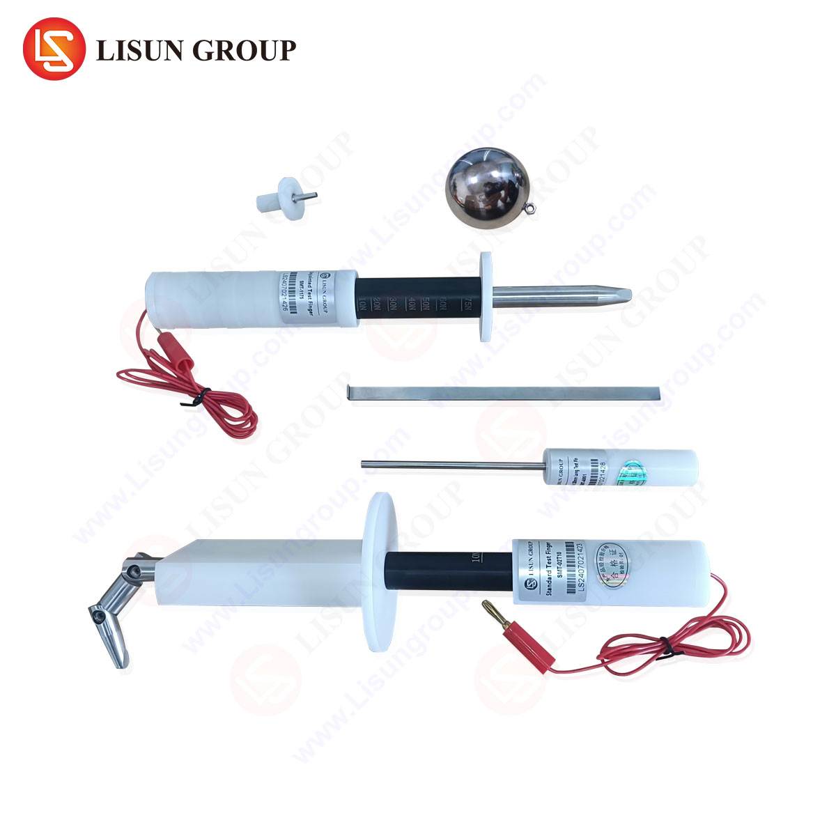
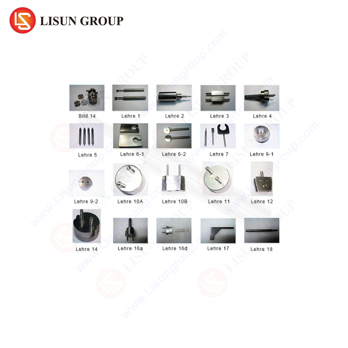
The theoretical performance of a socket contact is entirely contingent upon its adherence to precise dimensional tolerances. Verification of these tolerances is not achievable through simple calipers or micrometers due to the complex internal geometries and the necessity to assess functional fit. This is where specialized gauging apparatus becomes indispensable. The LISUN Gauges for Plugs and Sockets are engineered specifically for this purpose, providing a definitive, repeatable, and standardized method for assessing the compliance of BS 1363 socket-outlets.
The LISUN gauge system comprises a set of precision-machined pins and probes designed to simulate the dimensions of both standard and out-of-tolerance plug pins as defined in the standard. Key verification procedures include:
- Aperture Gauge Checks: Utilizing go/no-go gauges to verify that the Live and Neutral socket apertures fall within the permitted size range, preventing the use of undersized or oversized pins.
- Contact Force Measurement: A critical gauge measures the insertion and withdrawal force of a standardized pin. This provides a direct, albeit indirect, measurement of the contact normal force, ensuring it is within the safe and effective window specified by BS 1363-2.
- Earth Pin Proximity and Engagement Verification: Specialized gauges check the depth, alignment, and sequencing of the earth contact, ensuring the “early make, late break” safety feature is functionally present.
- Shutter Operation Testing: For shuttered sockets, gauges verify that the shutters operate correctly—opening only when a valid earth pin is inserted—and that they are robust enough to resist deliberate tampering.
The LISUN LS-CP-2 series, for example, is a comprehensive test apparatus that integrates these various gauge functions into a single, calibrated instrument. Its competitive advantage lies in its construction from hardened, dimensionally stable materials to resist wear, its traceable calibration to national standards, and its ergonomic design that allows for consistent application by quality control personnel. In a manufacturing environment, the use of such gauges is not merely a final inspection step but is integrated into the production line for statistical process control, enabling the early detection of tooling wear or process drift that could lead to non-conforming products.
Accelerated Lifecycle and Electrical Endurance Testing
Beyond initial dimensional checks, BS 1363-2 mandates severe performance tests that simulate years of service within a condensed timeframe. The mechanical endurance test requires the socket-outlet to withstand a minimum of 10,000 cycles of insertion and withdrawal of a test plug without failure. This test aggressively challenges the socket contacts’ resistance to mechanical wear and fatigue. Following this, the electrical endurance test subjects the worn socket to a further 1,000 cycles under full rated load, verifying that the contacts can still perform safely even after mechanical degradation.
These tests are designed to precipitate latent failures. A socket contact that has experienced significant stress relaxation will exhibit a sharp increase in temperature during the electrical endurance phase. The data gathered from thermocouples attached to the contacts during this test provides a direct measure of the contact’s long-term viability. The correlation between the initial normal force (as verified by LISUN gauges) and the performance in these endurance tests is strong, underscoring the predictive value of precise dimensional and force control during manufacturing.
Ensuring Compliance in a Global Manufacturing Landscape
With the globalized production of electrical accessories, the consistent application of standards is a significant challenge. Different manufacturing facilities may employ varying tooling, material batches, and assembly processes. The use of a standardized, unambiguous verification tool like the LISUN gauge system provides a common benchmark for quality. It allows brand owners, testing laboratories, and certification bodies worldwide to speak a common technical language, ensuring that a socket-outlet manufactured in one region provides the same level of safety and performance as one manufactured elsewhere.
This is particularly crucial for third-party test houses and national certification bodies, such as those granting the BSI Kitemark. Their reliance on precision gauges is absolute when determining whether a product sample conforms to BS 1363-2. The objectivity and repeatability offered by a well-designed gauge system are the bedrock of a trustworthy certification regime, preventing subjective interpretations and ensuring that only products that meet the stringent safety requirements of the standard enter the market.
Frequently Asked Questions (FAQ)
Q1: Why is the measurement of insertion and withdrawal force so critical for socket contact testing?
The insertion and withdrawal force, as measured by specialized gauges, serves as a direct proxy for the contact normal force. A force within the specified range indicates that the contact spring is providing sufficient pressure to ensure a low-resistance electrical connection without causing excessive wear on the plug pins or making insertion impractical for the user. Deviations from this range can signal issues with material temper, spring geometry, or surface finish.
Q2: How often should LISUN or similar compliance gauges be recalibrated in a quality control environment?
The recalibration interval depends on the frequency of use and the operating environment. In a high-volume manufacturing setting where gauges are used multiple times per shift, a quarterly or semi-annual recalibration schedule is typical. For less frequent use, such as in a laboratory audit capacity, an annual recalibration may suffice. The key is to maintain a metrologically traceable chain to national standards to ensure measurement integrity.
Q3: Can a socket-outlet pass dimensional gauge checks but still fail electrical tests?
Yes, this is a possible, though less common, failure mode. Passing dimensional checks confirms the socket’s geometry is correct. However, failure in electrical tests, such as excessive temperature rise, could be caused by factors not directly related to geometry. These include substandard contact material with poor conductivity, inadequate plating leading to high surface resistance, or internal contamination that impedes proper electrical interface.
Q4: What is the significance of the “early make, late break” feature verified by earth contact gauges?
This is a fundamental safety feature mandated by BS 1363. It ensures that when inserting a plug, the earth connection is established before the Live and Neutral pins make contact. Conversely, upon withdrawal, the earth pin is the last to disconnect. This sequencing guarantees that the appliance casing is always grounded before the circuit becomes live, and remains grounded until after the circuit is broken, thereby protecting the user from electric shock in the event of an internal fault.
Q5: Beyond gauges, what other manufacturing processes are critical for producing compliant BS 1363-2 socket contacts?
Critical processes include the precision stamping and forming of the phosphor bronze spring components to ensure consistent geometry and minimal internal stresses; the controlled electroplating process to apply a uniform and adherent tin coating; and the final heat treatment (aging) to stabilize the spring temper and mitigate long-term stress relaxation. Advanced manufacturers use automated optical inspection (AOI) to supplement gauge checks for initial component validation.