


A Technical Examination of BS 1363 Figure 10 Test Equipment for Plug and Socket Compliance Verification
Introduction to Dimensional Compliance in BS 1363 Safety Standards
The BS 1363 standard, governing the safety requirements for 13 A plugs, socket-outlets, adaptors, and connection units in the United Kingdom and numerous other territories, establishes a comprehensive framework to mitigate electrical risks. Among its most critical provisions are the dimensional tolerances specified for plug pins and socket-outlet contacts. Precise adherence to these geometric parameters is non-negotiable for ensuring safe electrical engagement, mechanical stability, and the correct operation of protective shutters. The standard’s Figure 10 provides the definitive dimensional blueprint for the test gauges used to verify these tolerances. Consequently, BS 1363 Figure 10 test equipment represents a fundamental tool in the manufacturer’s quality assurance arsenal and within independent certification bodies, serving as the objective arbiter of conformance for a primary safety characteristic.
The Geometrical Imperative: Pin and Socket Tolerancing in BS 1363
The functional safety of a plug-socket interface hinges on a delicate balance of electrical and mechanical design. Plug pins must be of a precise cross-section, length, and spacing to guarantee sufficient contact pressure within the socket-outlet’s contacts, thereby minimizing contact resistance and the associated risk of overheating. Simultaneously, dimensional compliance is intrinsically linked to the shutter mechanism mandated by BS 1363. Socket shutters, designed to prevent access to live contacts unless a compliant plug is inserted, are mechanically actuated by the specific geometry and insertion force of the earth pin. Deviations in pin dimensions—such as an undersized earth pin diameter or incorrect pin splay—can compromise this safety feature, either by failing to open the shutters with a legitimate plug or, more hazardously, permitting unauthorized access through improper means. The Figure 10 gauges are engineered to provide a binary, go/no-go assessment of these critical dimensions, removing subjectivity from the inspection process.
Deconstructing the Figure 10 Gauge Set: Form, Function, and Application
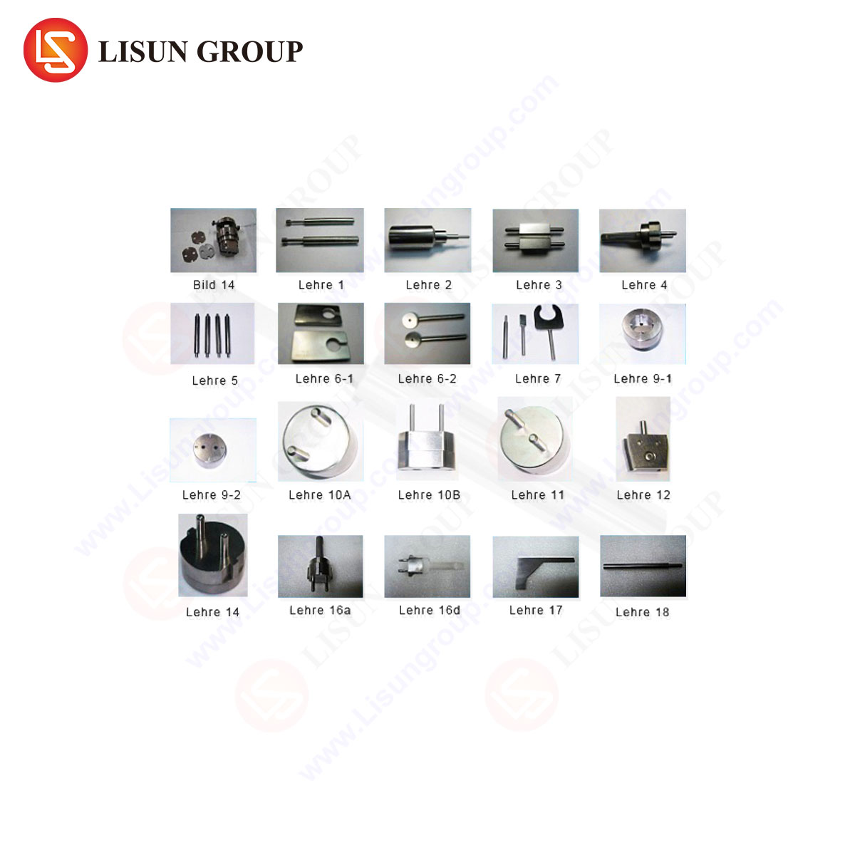
BS 1363 Figure 10 delineates a suite of gauges, each designed to test a specific dimensional attribute. A comprehensive set typically includes, but is not limited to, the following essential instruments:
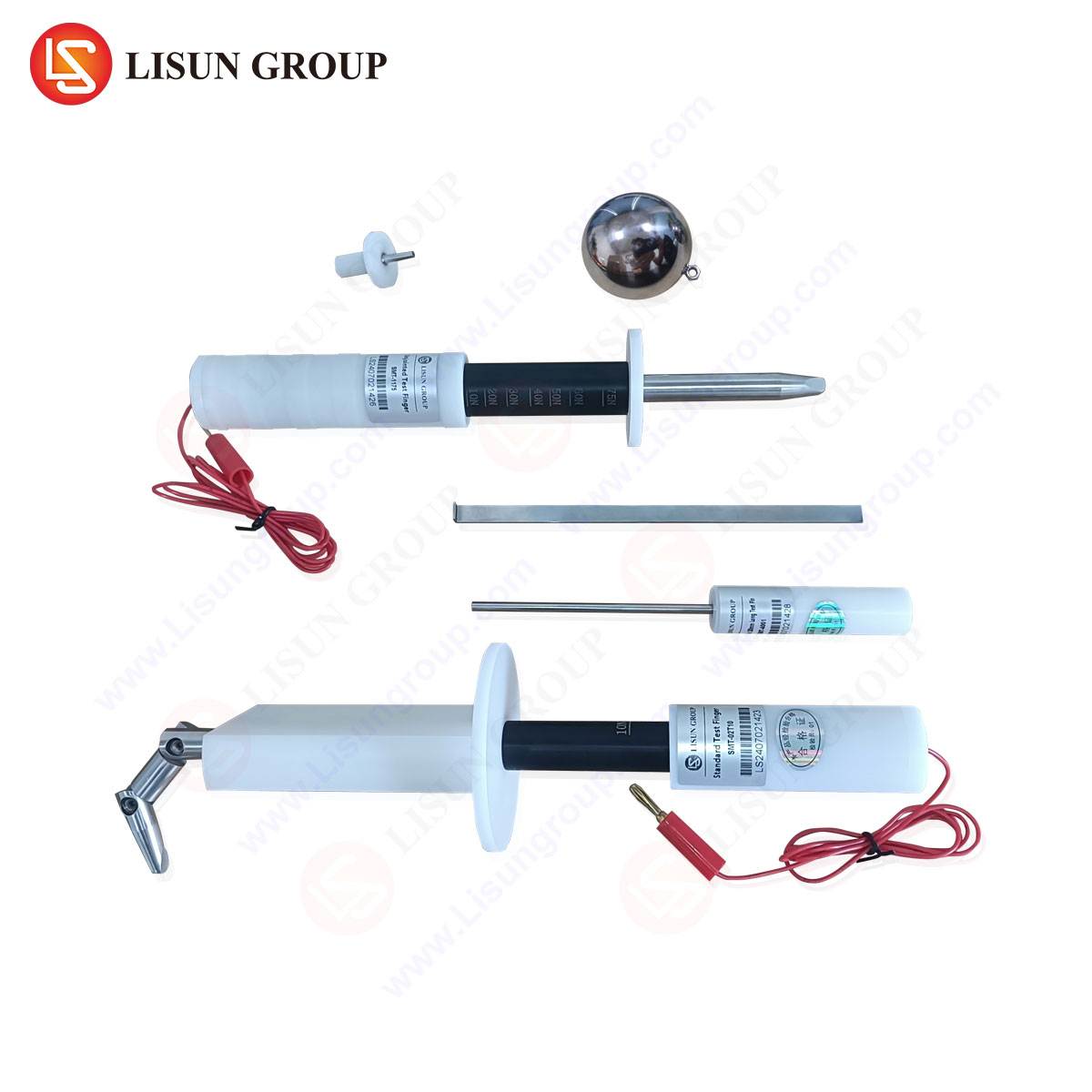
- The “Go” Gauge for Pin Assembly: This gauge verifies the maximum permissible overall dimensions of the plug pin assembly. It consists of a plate with apertures corresponding to the maximum allowed spread (splay) of the line and neutral pins relative to the earth pin, and the maximum permitted cross-sectional dimensions of all three pins. A compliant plug must freely enter the gauge under its own weight, demonstrating it is not oversized.
- The “No-Go” Gauge for Pin Assembly: Conversely, this gauge establishes the minimum permissible dimensions. Its apertures are configured to the minimum allowable pin splay and cross-sections. A compliant plug must not fully enter this gauge, ensuring the pins are not undersized or too close together, which would lead to poor socket contact.
- Pin Diameter and Length Gauges: Individual gauges are specified to check the diameter of the earth pin and the lengths of all pins. These often take the form of slot or hole gauges with precise tolerances, confirming each pin falls within its defined dimensional envelope.
- Socket-Outlet Contact Gauge (Test Pin): Perhaps the most critical gauge, this is a set of standardized test pins with defined dimensions, weights, and surface finishes. They are used to verify the contact force and engagement depth within the socket-outlet. The standard specifies insertion and withdrawal force measurements to ensure sufficient grip for electrical continuity without excessive resistance that could strain the plug or socket.
The application of these gauges follows a strict protocol outlined in the standard. For plugs, the gauges are applied under specified conditions—typically with the plug flexibly supported—to check for free entry or prohibited entry as required. For sockets, the test pins are inserted and connected to a force gauge to measure the contact force directly. The results provide unambiguous data on dimensional conformity.
LISUN Gauges for Plugs and Sockets: Engineered Precision for Compliance Assurance
Within the landscape of test equipment, the LISUN series of BS 1363 Figure 10 gauges has been developed to meet the exacting demands of high-volume production testing and rigorous laboratory certification. These instruments are not mere replicas of the dimensional drawings; they are precision-engineered measurement artifacts manufactured from hardened tool steel or other durable materials to resist wear and maintain calibration integrity over thousands of cycles.
The LISUN gauge set embodies several key design and performance principles. Each gauge is manufactured with tolerances significantly tighter than those it is intended to verify, ensuring the measurement uncertainty of the gauge itself is a negligible fraction of the product tolerance band. Surfaces subject to wear, such as the entry chamfers and aperture edges, are hardened and finely finished to prevent binding and ensure consistent, repeatable results. The sets are comprehensively traceable to national measurement standards, providing the metrological pedigree required for accredited testing laboratories.
A representative specification for a LISUN BS 1363 Figure 10 Gauge Set is outlined below:
| Component | Material | Hardness | Primary Function | Traceability |
|---|---|---|---|---|
| Go/No-Go Gauge Plate | High-Carbon Tool Steel | 58-62 HRC | Verifies max/min pin splay & cross-section | Dimensional report to UKAS standard |
| Earth Pin Diameter Gauge | Stainless Steel | 55-60 HRC | Checks compliance of earth pin diameter | Dimensional report to UKAS standard |
| Pin Length Gauge | Anodized Aluminum Alloy | N/A | Verifies pin lengths within tolerance | Dimensional report to UKAS standard |
| Socket Test Pin Set | Phosphor Bronze, Stainless Steel | Per BS 1363 | Measures socket contact force & engagement | Force calibration certificate |
The operational principle is one of absolute mechanical comparison. The LISUN gauges provide a physical manifestation of the tolerance limits. Their use in a production environment allows for rapid, operator-friendly inspection, segregating non-conforming components before they proceed to assembly. In a test laboratory, they serve as the definitive reference for type-testing and failure analysis, offering unambiguous evidence of compliance or deviation.
Industry Applications: From Factory Floor to Certification Laboratory
The deployment of Figure 10 test equipment spans the entire product lifecycle. In manufacturing quality control, gauges are used for incoming inspection of pin components, in-process checks during plug molding or assembly, and 100% final inspection or AQL (Acceptable Quality Level) sampling of finished goods. This frontline deployment prevents batch-level non-conformities.
For socket-outlet manufacturers, the test pin set is indispensable. It is used to validate the contact design of new socket models, perform routine production checks on contact spring force, and conduct durability testing by simulating thousands of insertions. A socket that fails to meet the specified contact force with a standard test pin risks overheating in the field.
Third-party certification bodies and test houses, such as those affiliated with BSI, Intertek, or SGS, rely on accredited gauge sets like those from LISUN to perform type-approval testing. Their findings form the technical basis for granting safety marks (e.g., the BS1 Kitemark). During market surveillance activities conducted by trading standards authorities, these same gauges provide the evidence for enforcing compliance, potentially leading to product recalls for systematically non-conforming goods.
Comparative Analysis: The Metrological Advantages of Dedicated Gauge Systems
While alternative measurement methods exist, such as coordinate measuring machines (CMM) or optical scanners, the dedicated Figure 10 gauge offers distinct advantages for this specific application. CMMs, though highly versatile and accurate, are relatively slow, require skilled operation, and are less suited to high-throughput production environments. Optical methods can struggle with certain edge conditions and material finishes.
The dedicated mechanical gauge system provides instantaneous, objective, and operator-intuitive results. The go/no-go outcome eliminates interpretation—the plug either fits or it does not. This speed and simplicity reduce training overhead and inspection cycle times dramatically. Furthermore, gauges like the LISUN series are designed for robustness in industrial settings, resisting environmental factors that might affect more sensitive electronic equipment. Their primary advantage is fitness-for-purpose: they are the most efficient and reliable tool for executing the specific pass/fail tests mandated by the standard.
Ensuring Measurement Integrity: Calibration and Maintenance Protocols
The authority of any test gauge is contingent upon its ongoing accuracy. A worn or damaged gauge can falsely accept non-compliant products or reject conforming ones, with significant safety and commercial consequences. Therefore, a rigorous calibration and maintenance regimen is essential.
Gauge sets should be calibrated at regular intervals, typically annually, by an accredited laboratory competent in dimensional metrology. Calibration involves verifying every critical dimension of the gauge against a reference standard traceable to national institutes. The resulting certificate provides documented evidence of the gauge’s conformance to the Figure 10 specifications at the time of calibration.
User maintenance involves proper storage in protective cases to prevent nicks or corrosion, periodic visual inspection for burrs or damage, and functional checks against a known-reference plug or master gauge. The use of a controlled master sample—a plug verified to be dimensionally central within the tolerance band—for daily or weekly system checks is a recommended best practice to ensure the ongoing health of the inspection process.
Conclusion: The Foundational Role of Dimensional Verification
BS 1363 Figure 10 test equipment, as exemplified by precision-engineered sets from manufacturers like LISUN, constitutes a fundamental pillar of electrical safety verification. By translating the abstract dimensional requirements of the standard into tangible, repeatable mechanical tests, these gauges provide an indispensable barrier against non-conforming products entering the supply chain. Their application across design validation, production control, and independent certification ensures the continued integrity of the plug and socket interface—a critical point of connection upon which everyday electrical safety reliably depends. The ongoing evolution of manufacturing techniques and materials will continue to demand the unwavering precision and reliability that dedicated, well-maintained gauge systems provide.
Frequently Asked Questions (FAQ)
Q1: How frequently should a BS 1363 Figure 10 gauge set be calibrated in a high-volume production environment?
A1: For a high-volume production setting, an annual calibration cycle by an accredited laboratory is the minimum recommended practice. However, the frequency should be risk-based. If gauges are used continuously across multiple shifts, or if a daily master sample check indicates potential drift, a more frequent interim verification (e.g., quarterly) may be justified. The calibration interval must be defined and justified within the organization’s quality management system.
Q2: Can a single “universal” test pin be used to check all socket-outlet contact forces, or is a full set necessary?
A2: A full set of test pins, as specified in BS 1363, is necessary. The standard defines different test pins for various tests, including those for initial contact force, durability testing after thousands of insertions, and tests with deliberately worn pins. Each pin has specified dimensions, weight, and surface finish. Using an incorrect or non-compliant pin will invalidate the force measurement and the test’s compliance with the standard.
Q3: What is the most common failure mode identified by the Figure 10 “No-Go” gauge during plug inspection?
A3: A frequent failure is the plug pins failing the “No-Go” test due to insufficient splay (the pins being too close together). This is often a result of mold wear or misalignment in the injection molding process for the plug body. An overly narrow pin assembly can lead to inadequate contact pressure in the socket, resulting in high resistance, overheating, and potential fire risk.
Q4: Are LISUN gauges suitable for testing both standard and reinforced insulation on plug pins?
A4: The dimensional gauges (Go/No-Go, diameter, length) are agnostic to insulation type as they measure the metallic pin geometry. However, the verification of insulation barriers and shrouding is covered by other clauses and tests within BS 1363 (e.g., creepage and clearance distances, impact tests). The Figure 10 gauges specifically address the dimensional conformity of the conductive parts and their basic assembly.
Q5: If a plug passes the Go gauge but fails the No-Go gauge, what does this indicate about its dimensional conformance?
A5: This result indicates that the plug’s pin assembly is dimensionally undersized. It is small enough to enter the minimum-limit (No-Go) gauge, which it should not. This means the pins are either too thin, too short in cross-sectional dimensions, or spaced too closely together. This is a critical non-conformance, as undersized pins will not make reliable, low-resistance contact in a socket-outlet.