


The Role of Precision Environmental Stress Testing in Product Reliability Engineering
In the development and validation of modern industrial and consumer products, the ability to predict and ensure operational reliability across diverse environmental conditions is paramount. Component failure due to thermal stress, humidity ingress, or rapid thermal cycling represents a significant risk to product safety, brand integrity, and operational longevity. Climate chambers, or environmental test chambers, serve as the foundational apparatus for simulating these conditions in a controlled, repeatable laboratory setting. These instruments are not merely boxes that alter temperature and humidity; they are sophisticated systems that enable engineers to accelerate time, compressing years of potential field exposure into days or weeks of rigorous testing. This article examines the technical principles, applications, and critical considerations of environmental testing, with a specific focus on the methodologies employed by thermal shock test chambers, exemplified by the LISUN HLST-500D model.
Fundamental Principles of Accelerated Environmental Stress Screening
Accelerated stress testing operates on established principles of failure physics, primarily leveraging the Arrhenius equation for temperature-induced failures and the Peck model for humidity-related failures. The core objective is to induce known failure mechanisms without introducing failure modes that would not occur in real-world use. A thermal shock chamber, distinct from a steady-state temperature/humidity chamber, applies extreme thermal transients. This rapid cycling between high and low temperature extremes induces mechanical stress due to the differential coefficients of thermal expansion (CTE) of bonded materials—such as silicon dies, solder joints, epoxy encapsulants, and metallic leads.
The efficacy of such testing hinges on the rate of temperature change and the dwell times at temperature extremes. A true thermal shock test, as defined by standards like IEC 60068-2-14, involves a rapid transfer of the test specimen between two independently controlled zones. This method subjects components to severe tensile and compressive forces, efficiently identifying latent manufacturing defects like micro-cracks in solder balls (BGA packages), delamination of conformal coatings, or compromised hermetic seals.
Architectural Configuration of a Three-Zone Thermal Shock System
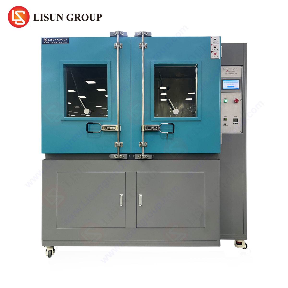
The LISUN HLST-500D Thermal Shock Test Chamber embodies a classic three-zone architectural configuration, comprising a high-temperature zone, a low-temperature zone, and a movable basket that houses the test specimens. This design is engineered to maximize transfer speed and temperature stability.
The high-temperature zone typically utilizes nickel-chromium alloy electric heaters with PID (Proportional-Integral-Derivative) control, capable of achieving and maintaining temperatures up to +200°C with minimal deviation (±2°C). The low-temperature zone employs a cascade refrigeration system, often using eco-friendly refrigerants like R404a or R23, to reach temperatures as low as -70°C. The heart of the system is the vertically moving test basket, driven by a high-torque motor and precision guide rails. Upon test initiation, the basket rapidly transfers the specimens from the ambient or dwell zone into one climatic extreme, then, after a programmed dwell period, swiftly moves them to the opposing zone. This transfer is typically achieved in less than 10 seconds, ensuring the specified thermal shock rate is maintained.
The chamber’s control system integrates a programmable logic controller (PLC) with a touch-screen human-machine interface (HMI). This allows for the precise programming of complex test profiles, including cycle count, dwell times (e.g., 30 minutes at each extreme), and optional intermediate stabilization steps. Data logging functionality is critical, recording both chamber air temperatures and, optionally, monitored specimen temperatures via external sensors for validation.
Technical Specifications and Performance Metrics of the HLST-500D
The performance of a thermal shock chamber is quantified by its specifications, which define its testing envelope and precision. The LISUN HLST-500D provides a standardized testing volume and performance profile suitable for component and sub-assembly level testing.
Table 1: Key Specifications of the HLST-500D Thermal Shock Test Chamber
| Parameter | Specification |
| :— | :— |
| Test Volume | 500 Liters (Internal dimensions customizable) |
| Temperature Range | High Temp Zone: +60°C to +200°C; Low Temp Zone: -10°C to -70°C |
| Heat-up Time | +25°C to +200°C within ≤ 25 minutes |
| Pull-down Time | +25°C to -70°C within ≤ 80 minutes |
| Recovery Time | ≤ 5 minutes after specimen transfer |
| Temperature Fluctuation | ≤ ±2.0°C |
| Temperature Uniformity | ≤ 2.0°C |
| Basket Transfer Time | ≤ 10 seconds |
| Control System | Programmable Touch-Screen PLC Controller |
| Data Recording | Standard USB or RS-485 interface for profile and result logging |
| Internal Material | Stainless Steel (SUS#304) |
| Insulation | High-density polyurethane foam |
These metrics are not arbitrary; they are designed to comply with and exceed the requirements of major international testing standards, including IEC 60068-2-14, MIL-STD-883, and JESD22-A104. The rapid transfer and recovery times are particularly crucial, as they ensure the specimen itself—not just the chamber air—experiences the intended thermal transient.
Industry-Specific Applications and Failure Mode Analysis
The application of thermal shock testing spans industries where electronic or electromechanical components face harsh operational environments or where reliability is non-negotiable.
- Automotive Electronics: Electronic control units (ECUs), sensors, and lighting modules are tested to simulate conditions from desert heat to arctic cold, often encountered in rapid succession. The HLST-500D can identify solder joint fatigue in power modules or connector integrity issues that could lead to brake system or engine management failures.
- Aerospace and Aviation Components: Avionics, satellite components, and communication systems undergo thermal shock testing to validate performance after exposure to the extreme temperature differentials between sun-facing and shadowed sides of an aircraft or spacecraft. Testing here focuses on the integrity of ceramic substrates and wire bond connections.
- Telecommunications Equipment: 5G base station components, optical transceivers, and outdoor switching gear must withstand daily and seasonal cycles. Thermal shock accelerates testing of plated through-holes (PTH) in PCBs and the stability of crystal oscillators.
- Medical Devices: Implantable devices and diagnostic equipment require absolute reliability. Testing can reveal delamination in encapsulated batteries or failure in micro-welds within a pacemaker due to CTE mismatch.
- Lighting Fixtures (LEDs): High-brightness LED arrays and drivers are subjected to thermal shock to assess the integrity of die-attach materials and phosphor layers, which directly impact lumen maintenance and color stability over the product’s lifespan.
- Electrical Components & Wiring Systems: Connectors, switches, and cable terminations are tested to ensure metal and plastic interfaces do not crack or lose contact pressure, which could cause arcing or increased resistance.
Comparative Advantages in Chamber Design and Operational Efficacy
The design philosophy behind a chamber like the HLST-500D incorporates several features that address common pain points in reliability testing. The independent three-zone design eliminates cross-contamination of thermal loads, allowing both extreme zones to remain at stable setpoints, thereby improving energy efficiency and reducing test cycle time compared to single-chamber, air-stream-based thermal shock systems. The use of a robust basket transfer mechanism with mechanical or pneumatic damping ensures smooth, reliable operation over tens of thousands of cycles, a necessity for high-volume production screening.
Furthermore, the cascade refrigeration system is engineered for maintainability and consistent performance at deep temperatures. Advanced insulation techniques minimize thermal leakage and frost formation, which can impede mechanical movement and affect uniformity. From a data integrity perspective, the inclusion of comprehensive audit trail capabilities and calibration ports for external sensor validation supports compliance with quality management systems like ISO/IEC 17025 for testing laboratories.
Integration into Product Development and Qualification Lifecycles
Implementing thermal shock testing is most effective when strategically integrated into the product development lifecycle. During the Design and Prototyping phase, it is used for design margin exploration and failure mode discovery. In Design Validation (DVT) and Production Validation (PVT), it forms a core part of the environmental stress suite to qualify the final design and manufacturing process. For Reliability Demonstration Testing (RDT), it is used in conjunction with other tests (vibration, HALT) to predict Mean Time Between Failures (MTBF). Finally, in Incoming Quality Control (IQC) or Production Screening, a chamber can be used to perform 100% testing or batch sampling to weed out infant mortality failures before products reach the field.
The data derived from HLST-500D testing—such as the number of cycles to failure for a given population—feeds directly into reliability growth models and informs corrective actions, whether in component selection, PCB layout, or assembly process parameters (e.g., reflow profile).
FAQ Section
Q1: What is the critical difference between a thermal shock test and a temperature cycling test?
A1: The primary difference is the rate of temperature change. Thermal shock testing, as performed by a three-zone chamber like the HLST-500D, involves an extreme, nearly instantaneous transfer between two temperature extremes (e.g., within 10 seconds), focusing on mechanical stress from CTE mismatch. Temperature cycling typically occurs in a single chamber with a slower, controlled ramp rate (e.g., 5°C/min), which may also include humidity and is better for simulating slower, diurnal cycles.
Q2: How do you determine appropriate dwell times for a thermal shock test profile?
A2: Dwell times are not arbitrary; they must be sufficient for the test specimen to achieve thermal equilibrium throughout its mass. This is often determined empirically by placing thermocouples on or within a representative sample and monitoring until the temperature stabilizes at the setpoint. Standards often suggest a minimum dwell (e.g., 30 minutes), but the actual time should be based on the thermal mass of the product under test.
Q3: Can the HLST-500D be used for testing with powered devices (active testing)?
A3: While the primary function is passive thermal shock, most chambers of this class, including the HLST-500D, can be fitted with electrical feed-through ports. This allows for in-situ power application and functional monitoring of devices during the test, enabling the detection of intermittent failures that occur only at specific temperature transitions.
Q4: What maintenance is required to ensure the long-term accuracy and reliability of the chamber?
A4: Regular preventive maintenance is crucial. This includes cleaning the air ducts and evaporators to ensure proper airflow, checking and tightening mechanical fasteners on the basket assembly, verifying the integrity of door seals, and calibrating temperature sensors annually against a NIST-traceable standard. The refrigeration system also requires periodic checks for refrigerant charge and compressor oil.
Q5: How does the chamber ensure temperature uniformity across the test basket?
A5: Uniformity is achieved through a combination of optimized airflow design, strategically placed fans and baffles in each zone, and high-quality insulation. The chamber is validated by mapping temperatures at multiple points within the empty workspace (per ASTM E1459 or similar). For loaded testing, the arrangement of specimens must not obstruct this engineered airflow to maintain specified uniformity.