


The Role of Precision Environmental Stress Screening in Modern Product Validation
The relentless drive for miniaturization, increased functionality, and global market deployment across high-technology industries has rendered product reliability a non-negotiable cornerstone of design and manufacturing. Components and assemblies are routinely subjected to environmental conditions far more extreme and variable than the controlled ambiance of a laboratory or production floor. Consequently, the ability to accurately simulate and accelerate these conditions through controlled testing is paramount. Climate test chambers, sophisticated instruments designed for environmental stress screening (ESS), have thus evolved from ancillary quality checks to integral components of the product development lifecycle. These systems enable engineers to precipitate latent defects, validate design limits, and predict field performance under a vast spectrum of temperature and humidity parameters.
Fundamental Operational Principles of Climatic Simulation
At its core, a climate test chamber operates on the principle of creating a precisely controlled, isolated atmospheric environment. This is achieved through the synergistic integration of several key subsystems: a thermally insulated test workspace, a refrigeration circuit, a heating system, a humidity generation and condensation unit, and a sophisticated digital controller. The refrigeration circuit, typically employing a cascade compressor system for lower temperature ranges, extracts thermal energy from the test space. Conversely, resistive heating elements introduce energy to elevate the temperature. Humidity is introduced via a boiler system that injects steam, while dehumidification is often accomplished by cooling the air below its dew point within a dedicated channel, causing water vapor to condense and be removed, after which the air is reheated to the desired dry-bulb temperature.
The precision of this simulation hinges on the control system’s ability to manage the interaction between these subsystems. Modern chambers utilize programmable controllers with multi-channel PID (Proportional-Integral-Derivative) logic to manage temperature and humidity independently yet cohesively. This allows for the execution of complex profiles, including steady-state dwells, rapid ramps, and cyclic conditions, replicating everything from the diurnal cycle of a desert to the persistent dampness of a tropical climate. Sensor fidelity, typically via platinum resistance thermometers (PRTs) and capacitive polymer humidity sensors, is critical for feedback, ensuring the setpoint parameters are maintained with minimal deviation.
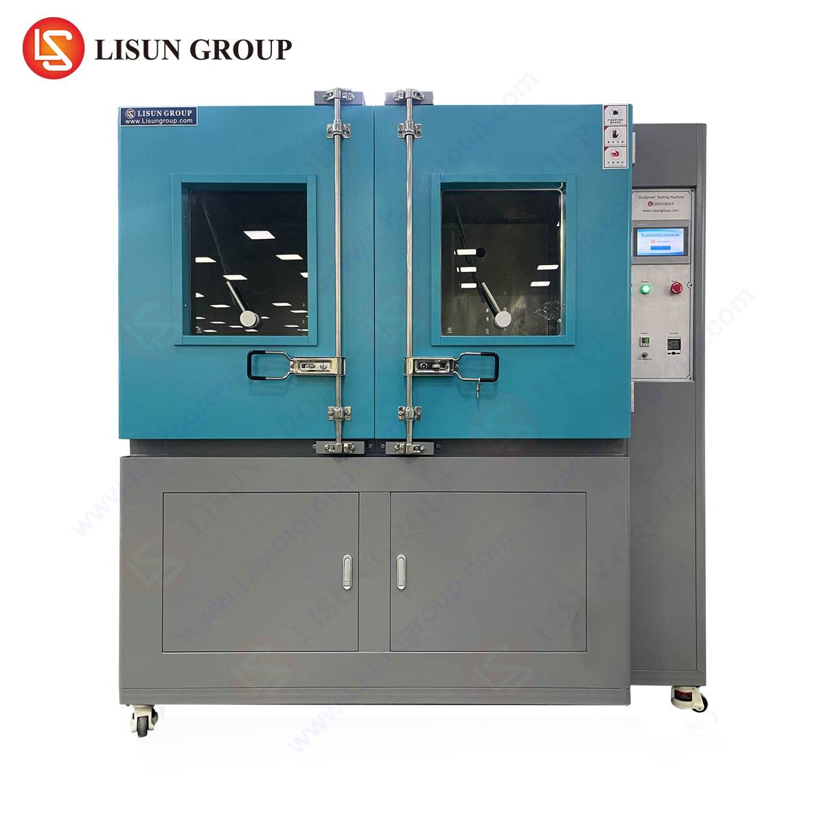
Introducing the HLST-500D Thermal Shock Test Chamber
While steady-state and cyclic temperature-humidity testing is essential for evaluating material stability and operational lifespan, many components face a more abrupt form of stress: rapid thermal transition. This is the specific domain of the thermal shock test chamber, such as the LISUN HLST-500D. Unlike single-compartment chambers, the HLST-500D employs a three-zone architecture (high-temperature zone, low-temperature zone, and a test basket that transitions between them) to subject products to extreme temperature variations in a matter of seconds, simulating shocks experienced during power cycling, geographic transportation, or sudden environmental exposure.
The testing principle is one of transfer. The test specimens are placed in a moving basket. The chamber preconditions two separate air chambers to vastly different setpoints—for example, +150°C and -65°C. Upon initiation of a test cycle, the basket automatically transfers the specimens from the high-temperature zone to the low-temperature zone, or vice-versa, within a transfer time typically specified at less than 10 seconds. This rapid movement minimizes temperature stabilization during transfer, ensuring the component itself, not just the surrounding air, experiences the full thermal shock. The dwell time at each extreme is fully programmable, allowing for stabilization of the specimen’s internal temperature before the next transition.
Key Specifications of the HLST-500D:
- Test Zones: Three independent zones (High Temp, Low Temp, Transition).
- Temperature Range: High Temp Zone: +60°C to +200°C; Low Temp Zone: -10°C to -65°C (or -80°C with optional LN2 boost).
- Recovery Time: ≤5 minutes (from +150°C to -55°C or vice-versa after specimen load).
- Basket Transfer Time: <10 seconds.
- Basket Load Capacity: Standard configuration supports up to 15kg.
- Control System: Digital touch-screen programmable controller with data logging and USB interface.
- Internal Dimensions: Customizable, but a standard model offers approximately 500 liters of test volume across the zones.
- Safety Features: Over-temperature protection, compressor delay protection, phase failure protection, and audible alarms.
Industry-Specific Applications and Failure Mode Precipitations
The HLST-500D’s capability to induce rapid, severe thermal stress makes it an indispensable tool for identifying failure modes related to coefficient of thermal expansion (CTE) mismatches, solder joint integrity, and material fatigue.
Automotive Electronics & Aerospace Components: Modern vehicles and aircraft incorporate dense electronic control units (ECUs), sensors, and connectivity modules. An engine control module may experience a temperature swing from winter cold-start to under-hood operational heat within minutes. The HLST-500D accelerates this, precipitating cracks in PCB vias, delamination of ceramic substrates, or failure of wire bonds within integrated circuits. Aerospace avionics must withstand the rapid decompression and cooling at altitude after ground operation.
Telecommunications Equipment and Electrical Components: Base station electronics, fiber optic transceivers, and high-power switches are subject to daily and seasonal cycles. Thermal shock testing validates the robustness of solder balls in BGA (Ball Grid Array) packages and the integrity of plated through-holes. A faulty socket or switch that undergoes rapid expansion and contraction can develop contact resistance, leading to arcing and failure.
Lighting Fixtures and Consumer Electronics: LED-based lighting, particularly for automotive or outdoor use, experiences rapid on-off cycling, generating significant junction temperature swings. The HLST-500D tests the integrity of the LED die attach, the wire bonds, and the seals around the lens assembly. Similarly, a smartphone left in a car may quickly move from a freezing overnight temperature to a sun-heated interior, testing the adhesion of display layers and the performance of the battery.
Medical Devices and Industrial Control Systems: Implantable devices or portable diagnostic equipment must maintain functionality after sterilization (thermal or chemical shock) and during transport. Industrial PLCs (Programmable Logic Controllers) in unheated factories can be shocked by the heat generated from startup of heavy machinery. Testing reveals weaknesses in conformal coatings, battery contacts, and encapsulated sensors.
Standards Compliance and Validation Rigor
The deployment of chambers like the HLST-500D is not arbitrary; it is guided by international standards that define test severity, duration, and pass/fail criteria. Compliance ensures that test results are reproducible, comparable, and recognized across global supply chains. Key standards referencing thermal shock testing include:
- IEC 60068-2-14: Environmental testing – Part 2-14: Tests – Test N: Change of temperature.
- MIL-STD-883, Method 1010.9: Test Method Standard for Microcircuits – Temperature Cycling.
- JESD22-A104: Temperature Cycling.
- ISO 16750-4: Road vehicles – Environmental conditions and testing for electrical and electronic equipment – Part 4: Climatic loads.
- GB/T 2423.22: Chinese national standard for environmental testing for electric and electronic products – Test N: Change of temperature.
Adherence to these standards requires the chamber itself to meet strict performance metrics for temperature uniformity, rate of change, and recovery time, all of which are defining characteristics of the HLST-500D’s design.
Comparative Advantages in Engineering Design and Operational Efficiency
The technical architecture of the HLST-500D confers several distinct advantages in a production or qualification laboratory setting. Its three-zone design is inherently more energy-efficient during repetitive cycling than systems that must rapidly heat and cool a single volume. The separation of hot and cold zones allows each refrigeration and heating system to operate at optimal efficiency, maintaining setpoints with minimal compensatory effort. The vertical basket transfer mechanism, driven by a robust pneumatic or electrical system, ensures reliable, high-speed movement critical for achieving the specified shock rate.
Furthermore, the use of advanced insulation materials and high-quality sealants on the basket and chamber doors minimizes thermal leakage and frost formation, enhancing long-term stability and reducing maintenance downtime. The programmability of the controller allows for the creation of highly specific test profiles—beyond simple two-zone shocks—to include intermediate stabilization steps or complex multi-stage cycles, accommodating even the most stringent proprietary corporate test standards.
From a practical standpoint, the chamber’s data logging capabilities provide an immutable record of the test parameters versus time, essential for audit trails and failure analysis reports. The ability to simulate years of field thermal stress in a matter of days or weeks enables faster time-to-market while simultaneously elevating the demonstrated reliability of the final product, reducing warranty claims and field failure rates.
Integrating Thermal Shock into a Comprehensive Reliability Strategy
It is critical to position thermal shock testing not as a standalone activity, but as one vital element within a broader Highly Accelerated Life Test (HALT) or Environmental Stress Screening (ESS) regimen. The HLST-500D is exceptionally effective at finding gross manufacturing defects and design weaknesses related to thermal mechanical stress. However, its findings are often most informative when correlated with those from other tests. A component that survives thermal shock may then be subjected to prolonged temperature-humidity bias (THB) testing to evaluate electrochemical migration. Conversely, a failure precipitated in thermal shock can be root-cause analyzed, leading to a design improvement that is subsequently validated with vibration and combined environment testing.
This integrated approach is particularly relevant for complex systems. For example, an automotive LED headlamp assembly might first undergo thermal shock in the HLST-500D to test its physical integrity, followed by a cyclic humidity test to evaluate lens fogging, and finally a photometric test to ensure light output remains within specification after stress. This layered validation strategy, enabled by precise and reliable equipment, is what ultimately defines product robustness in today’s competitive and liability-conscious markets.
Frequently Asked Questions (FAQ)
Q1: What is the critical difference between a thermal shock test chamber like the HLST-500D and a standard temperature cycling chamber?
A1: The fundamental difference lies in the rate of temperature change. A standard temperature cycling chamber changes the temperature of a single workspace at a controlled ramp rate (e.g., 5°C/min). A thermal shock chamber uses separate hot and cold zones and a moving basket to achieve an extremely rapid transfer, subjecting the specimen to a near-instantaneous change in the ambient temperature, thereby inducing a more severe thermal stress within the specimen itself.
Q2: For testing automotive electronics to ISO 16750-4, is the HLST-500D suitable for all test severities?
A2: The HLST-500D, with its standard range of -65°C to +150°C (extendable), is suitable for the majority of severities defined in ISO 16750-4, which commonly specify extremes such as -40°C to +125°C. Its rapid recovery and transfer times meet the stringent requirements for test profile accuracy. Engineers must always cross-reference the specific severity codes from their product’s requirement document with the chamber’s performance specifications.
Q3: How is the load capacity of the chamber determined, and what happens if it is exceeded?
A3: The load capacity (e.g., 15kg for the HLST-500D) refers to the maximum mass of the test specimens and their fixtures. Exceeding this capacity can strain the basket transfer mechanism, increase transfer time, and impair the chamber’s ability to recover temperatures quickly after the basket movement, thereby invalidating the test conditions. Thermal mass of the load is also a critical factor; highly massive specimens may not achieve the intended internal temperature shock within the specified dwell time.
Q4: Can the chamber be used for passive components like cables and connectors, or is it only for active electronics?
A4: Absolutely. Passive components are major beneficiaries of thermal shock testing. Cables, wiring harnesses, and connectors suffer from repeated expansion and contraction which can lead to insulation cracking, contact fretting corrosion (if seals are compromised), and a loss of mechanical retention. The HLST-500D is extensively used to qualify these components for use in environments with large temperature swings.
Q5: What are the primary maintenance considerations to ensure the HLST-500D’s long-term calibration and performance?
A5: Regular maintenance is crucial. Key tasks include: periodic cleaning of the air ducts and evaporators to prevent airflow restriction; checking and tightening door seals to prevent thermal leakage; verifying the calibration of temperature sensors annually against a NIST-traceable standard; and ensuring the pneumatic system (if equipped) has clean, dry air and that lubricants are applied as specified. A log of all maintenance and calibration events should be maintained for quality assurance purposes.