


A Comprehensive Guide to CEE7 C13 Plug and Socket Gauges: Principles, Standards, and Verification Methodologies
Introduction to Plug and Socket Gauge Systems
The global trade of electrical accessories necessitates rigorous conformity assessment to ensure safety, interoperability, and compliance with regional standards. Within the framework of the CEE7 standard, which governs plug and socket systems primarily used across continental Europe and other regions, the C13 connector—a standardized two-pole, side-earth plug and socket-outlet—represents a critical interface for countless electrical appliances. The physical dimensions and mechanical properties of these components are not subject to interpretation; they are precisely defined by international and national specifications. Consequently, the role of dedicated plug and socket gauges transitions from a mere quality control tool to an indispensable instrument for manufacturers, testing laboratories, and certification bodies. These gauges provide the definitive, objective means to verify that produced components adhere to the mandated geometric tolerances, thereby mitigating risks associated with poor contact, overheating, and user injury.
Anatomy of the CEE7 C13 Standard: Dimensional Tolerances and Critical Parameters
The CEE7 C13 system is characterized by its two round pins, 4.8 mm in diameter, spaced 19 mm between centers, and a side earthing contact. The governing standards, such as EN 50075, specify not only these primary dimensions but a comprehensive set of complementary measurements. These include pin length, the diameter and profile of the insulated sleeves, the dimensions and positioning of the earthing contact, and the overall plug profile. Crucially, the standard defines both “go” and “no-go” conditions. A compliant plug must fit into the “go” gauge with minimal, specified force, ensuring it is not too large. Simultaneously, it must not fit into the “no-go” gauge, which represents the maximum permissible dimensions, ensuring it is not too small or misshapen to make a safe, reliable connection. Socket-outlets are verified with corresponding pin gauges to ensure they accept compliant plugs without undue play or excessive force, while rejecting non-compliant or hazardous insertions.
The Metrological Foundation of Gauge Design and Manufacturing
The efficacy of any verification gauge is predicated on its own dimensional accuracy and material integrity. Master gauges, traceable to national metrological institutes, form the primary reference. Working gauges used in production environments are then manufactured to tolerances significantly tighter than those permitted for the plugs and sockets themselves—often an order of magnitude more precise. Material selection is paramount; gauge blocks are typically fabricated from hardened tool steel, stainless steel, or specialized alloys to resist wear, corrosion, and deformation under repeated use. Surface finish, often measured in Ra values, is critical to ensure smooth operation without binding, which could yield false “no-go” results. The design must also account for thermal expansion coefficients to maintain accuracy across the operational temperature range of a quality control laboratory or factory floor.
LISUN Gauges for Plugs and Sockets: A System for Conformity Verification
LISUN produces a comprehensive suite of gauges designed explicitly for the verification of CEE7 C13 plugs and socket-outlets, engineered to meet the exacting requirements of IECEE CB Scheme testing and national certification bodies. The LISUN system is modular, encompassing separate gauge sets for plugs and for sockets, each addressing the full spectrum of dimensional checks mandated by the standard.
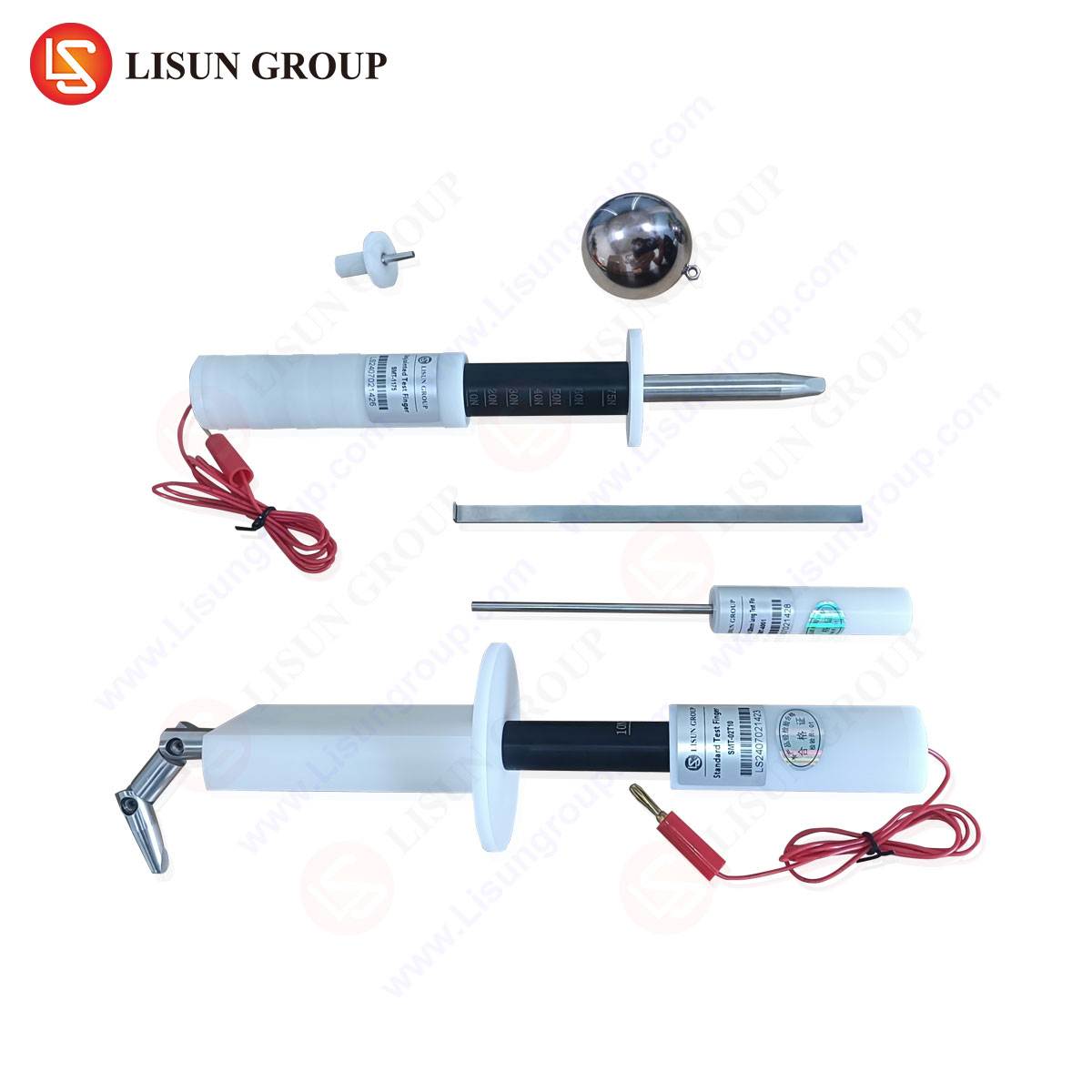
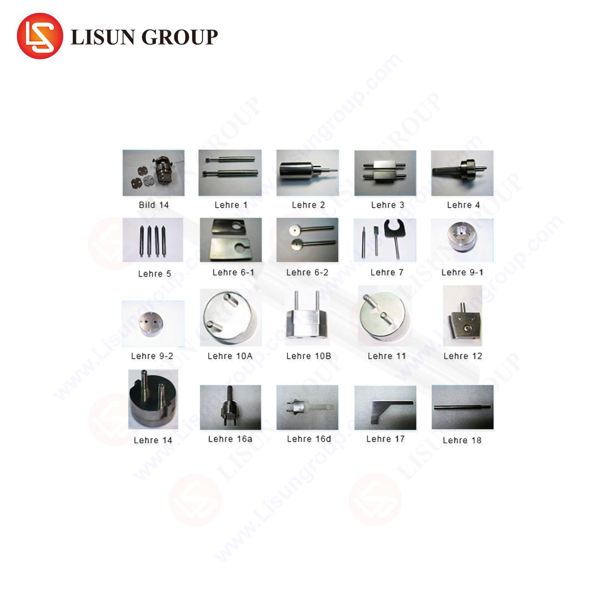
For plug testing, the LISUN kit includes:
- A “Go” Gauge: A precision-machined block simulating the minimum socket dimensions. A compliant plug must fully enter under its own weight or with minimal prescribed force.
- A “No-Go” Gauge: This gauge represents the maximum socket cavity dimensions. A compliant plug must not enter, or its pins must not make contact, when a defined test force is applied.
- Pin Gauges: Individual cylindrical gauges for verifying the diameter of live and neutral pins (4.8 mm) and the earthing contact.
- Profile and Check Gauges: For assessing the plug’s outline, pin spacing (19 mm center-to-center), and the configuration of the insulated sleeves.
For socket-outlet testing, the corresponding LISUN kit features:
- Standard Test Pin Assembly: A device with pins of exact maximum dimensions to verify that a socket accepts a plug without excessive force.
- Force Application Gauges: Mechanisms to apply standardized insertion and withdrawal forces to test the gripping strength of the contacts.
- Socket Entry Gauge: To verify the size and shape of the socket aperture.
Operational Principles and Testing Protocols in Industrial Settings
The application of these gauges follows a formalized sequence. For a production batch of C13 plugs, a statistically significant sample is first subjected to visual inspection before dimensional verification. The plug is offered to the “go” gauge; a failure to seat fully indicates the plug is oversized, which could damage sockets or fail to connect. It is then presented to the “no-go” gauge; if it seats, the plug is undersized, risking poor electrical contact, arcing, and overheating. Pin diameter and spacing are verified with the respective pin and spacing gauges. Socket testing is equally systematic, using the test pin assembly to simulate plug insertion and specialized gauges to measure contact grip and aperture geometry. Data from these tests are recorded for quality assurance audits and compliance documentation.
Competitive Advantages of Precision-Engineered Gauge Systems
In a market where safety is non-negotiable, the advantages of a gauge system like LISUN’s are multifaceted. First is metrological traceability and certification: Each gauge set is supplied with a calibration certificate from an accredited laboratory, ensuring measurements are internationally recognized. Second is durability and wear resistance: The use of high-grade materials and advanced surface treatments extends service life, maintaining calibration integrity over thousands of cycles and reducing long-term cost of ownership. Third is ergonomic and functional design: Gauges are configured for intuitive, repeatable operation by technicians, minimizing human error and test time. Finally, comprehensive coverage: Offering a complete kit for both plug and socket testing eliminates the need to source gauges from multiple suppliers, ensuring consistency and simplifying procurement and inventory management for testing laboratories and high-volume manufacturers.
Integration within Quality Management and Certification Frameworks
The use of standardized gauges is not an isolated activity but a integrated node within a manufacturer’s Quality Management System (QMS) and the broader product certification ecosystem. During initial type testing for marks such as the CE mark, VDE, or IMQ, independent laboratories will employ their own reference gauges to validate product designs. For ongoing production surveillance, manufacturers utilize gauges like those from LISUN for in-process and final inspection, creating auditable records of conformity. This data is vital for demonstrating due diligence and maintaining certification under schemes like the IECEE CB Scheme, which facilitates international market access. The gauge thus becomes a tangible link between the abstract language of a standard and the physical product on the production line.
Future Trajectories: Automation and Digital Data Integration
The evolution of gauge technology is moving towards increased automation and data integration. Manual gauge use, while fundamentally sound, is being supplemented by semi-automated and fully automated test stations. These systems can mechanically manipulate the gauge and test sample, apply precisely controlled forces, and integrate optical measurement systems for additional checks. The next generation of “smart gauges” may incorporate sensors and data loggers to automatically record each measurement, timestamp it, and feed results directly into a Statistical Process Control (SPC) software suite. This allows for real-time trend analysis, predictive maintenance of molding tools, and instantaneous non-conformance alerts, elevating quality control from a discrete inspection step to a continuous, data-driven feedback loop within smart manufacturing environments.
Conclusion
The CEE7 C13 plug and socket gauge represents a deceptively simple yet profoundly critical instrument in the electrical manufacturing industry. It is the physical embodiment of a safety standard, the final arbiter of dimensional compliance. As global supply chains demand ever-greater consistency and as safety regulations evolve, the reliance on precise, reliable, and traceable verification tools becomes absolute. Systems such as those manufactured by LISUN provide the necessary technical rigor, transforming the qualitative requirements of a written standard into quantitative, repeatable, and defensible measurements that safeguard product integrity, ensure regulatory compliance, and ultimately protect end-users.
FAQ Section
Q1: How frequently should plug and socket gauges be recalibrated?
A1: Calibration intervals depend on usage frequency, environmental conditions, and the quality management system requirements. For high-volume production testing, annual recalibration by an accredited laboratory is typical. Gauges used in reference or certification labs may follow a stricter schedule, such as biannually. The gauge’s calibration certificate will provide a recommended interval, but the user’s QMS should define the formal procedure based on risk assessment.
Q2: Can a single gauge set be used for both CEE7 C13 and similar-looking plugs from other standards?
A2: No. While some plug types may appear visually similar, dimensional tolerances (e.g., pin diameter, spacing, sleeve profile) are often subtly different between standards (e.g., CEE7 C13 vs. Australian AS/NZS 3112). Using an incorrect gauge will yield invalid results and potentially allow non-compliant, unsafe products to pass. It is imperative to use gauges specifically designed and calibrated for the exact standard being evaluated.
Q3: What are the most common failure modes identified by these gauges during production?
A3: Common plug failures include oversized pins or body (failing the “go” test) due to mold wear or injection pressure issues, and undersized pins (failing the “no-go” test) due to material shrinkage or incomplete mold filling. Incorrect pin spacing is another critical failure. For sockets, typical failures involve contact apertures that are too tight (excessive insertion force) or too loose (insufficient contact grip), both identified by the standard test pin assembly and force gauges.
Q4: Beyond dimensional checks, what other tests are required for full CEE7 C13 compliance?
A4: Dimensional verification is only one part of a comprehensive type test. Additional mandatory tests include electrical rating verification, temperature rise testing under load, mechanical endurance (insertion/withdrawal cycles), resistance to heat, ball pressure, and flammability, insulation resistance, dielectric strength (hi-pot), and tests for resistance to arcing and tracking. Gauges are essential for the initial dimensional compliance, which is a prerequisite for many of these subsequent electrical and mechanical tests.