


A Comprehensive Guide to CEE7 C13 Plug and Socket Gauges: Principles, Standards, and Verification Methodologies
Introduction to the CEE7 C13 Interface Standard
The CEE7 C13 plug and socket configuration represents a critical, standardized interface within the European and international electrical accessory landscape. Predominantly utilized for information technology equipment, desktop computers, monitors, and various office appliances, this two-pole, earthless connector system is defined by its two round pins spaced 13 millimeters apart, with a nominal diameter of 4.0 millimeters. Its counterpart, the CEE7 C14 inlet, is commonly integrated into power supply units. The ubiquity and simplicity of this interface necessitate rigorous dimensional and safety compliance to ensure interoperability, user safety, and long-term reliability. Verification of this compliance is not a matter of subjective assessment but requires precise, calibrated measurement tools known as plug and socket gauges. These instruments serve as the definitive arbiter between conformance and non-conformance to the geometric and mechanical tolerances stipulated in standards such as IEC/EN 60320-1 and IEC/EN 60320-2-2.
The Imperative of Dimensional Verification in Connector Safety
Electrical safety and mechanical performance are intrinsically linked to dimensional accuracy. A plug with undersized pins may result in poor electrical contact, leading to increased contact resistance, localized heating, and potential thermal failure. Conversely, oversized pins can exert excessive force on socket contacts, causing permanent deformation, loss of contact pressure over time, and difficulty of insertion or withdrawal. The socket aperture dimensions are equally critical; excessive clearance can permit unsafe wobble or misalignment, while insufficient clearance may prevent insertion of compliant plugs. Furthermore, standards define critical “checking gauges” to verify safety features like the recessed entry of socket apertures, which prevents accidental contact with live parts. Without objective gauge-based testing, manufacturers risk producing components that, while seemingly functional, may violate safety margins, leading to field failures, non-compliance with regulatory directives (e.g., the Low Voltage Directive), and potential liability.
Deconstructing the Gauge Set: Functional Components and Their Roles
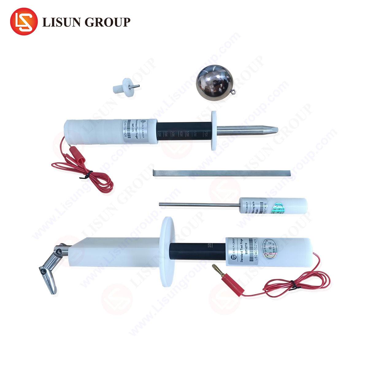
A comprehensive gauge set for the CEE7 C13 system is not a single tool but a collection of specialized instruments, each designed to verify a specific parameter. A typical set includes a plug gauge, a socket gauge, and often supplementary pin gauges.
The Plug Gauge (or “Go/No-Go” gauge for plugs) is a precision-machined metal block simulating the maximum and minimum allowable dimensions of a standard socket. A compliant plug must insert fully into the “Go” side with only the force expected from a standard socket, verifying that it is not oversized. It must not enter the “No-Go” side, which represents the minimum socket dimensions, ensuring the plug is not undersized and will maintain adequate contact pressure in a real socket.
The Socket Gauge (or “Go/No-Go” gauge for sockets) is a simulated plug with pin sections of precise diameters. The “Go” pins, at the minimum allowable pin size, must insert fully into the socket under a specified force, confirming the socket aperture is not too small. The “No-Go” pins, at the maximum allowable pin size, must not insert, verifying the socket does not offer excessive clearance that could compromise contact stability.
Supplementary pin gauges may be used for direct measurement of plug pin diameters, while recess gauges verify the depth of the socket shroud to ensure live parts are adequately protected. Each gauge is manufactured from hardened tool steel or similar durable material to resist wear from repeated use, with tolerances typically held to within ±0.01 mm to ensure measurement integrity.
Testing Principles and Metrological Foundations
The underlying principle of gauge testing is attribute gaging—determining whether a feature falls within a predefined tolerance zone, rather than providing a variable measurement. This pass/fail methodology is highly efficient for production line quality control. The process is governed by strict protocols: gauges must be used at standard atmospheric conditions to mitigate thermal expansion effects; insertion forces are applied consistently via calibrated spring mechanisms or specified weights; and gauges themselves undergo regular calibration against master gauges traceable to national metrology institutes.
The design of these gauges incorporates the “Taylor Principle,” which states that the “Go” gauge should check all related dimensions simultaneously (form and size), while the “No-Go” gauge checks each critical dimension individually. For a C13 plug gauge, the “Go” side checks the composite effect of pin diameter, pin spacing, and pin length. The “No-Go” side primarily verifies the pin spacing and the virtual size created by pin diameter. This approach ensures functional interchangeability.
LISUN Gauges for Plugs and Sockets: A Specification and Application Analysis
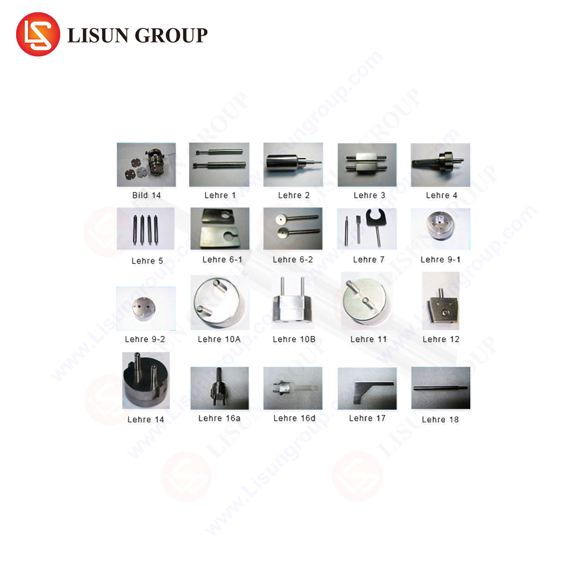
LISUN produces a range of precision test gauges for CEE7 C13 and other connector types, designed for use by manufacturers, testing laboratories, and quality assurance departments. Their gauge sets are engineered to provide reliable, repeatable compliance verification.
Specifications and Design Features: LISUN C13 gauge sets are typically machined from high-carbon chromium steel, hardened to HRC 58-62, and precision ground to achieve the surface finish and dimensional accuracy required by IEC/EN 60320. The gauges feature clear, permanent marking of “GO” and “NO GO” sections, along with the standard reference (e.g., C13). Pins and apertures are manufactured to the limit dimensions defined in the relevant standards. The sets are often supplied in protective cases with calibration certificates traceable to CNAS (China National Accreditation Service) or international equivalents, documenting the measured actual values of the gauge dimensions.
Industry Use Cases: The primary application is in Production Quality Control (QC), where random samples from the production line are tested to catch drifts in molding or stamping processes. In Incoming Quality Inspection (IQC), assemblers of finished goods use the gauges to verify components from subcontractors before integration. Third-Party Testing Laboratories and Certification Bodies (such as those providing UL, TÜV, or Intertek certification) utilize these gauges as part of their type-test and surveillance audit protocols to validate compliance with safety standards.
Competitive Advantages: LISUN gauges position themselves within the market through several technical and practical merits. The use of wear-resistant materials extends service life and calibration intervals, reducing total cost of ownership. The traceable calibration provided enhances credibility for audits and compliance reporting. Furthermore, LISUN often offers complete system solutions, including gauges for related standards (C5, C7, C19, etc.), providing consistency across a manufacturer’s test bench. Their design emphasizes ergonomic handling, with knurled grips or handles on plug gauges to ensure proper axial force application during testing.
Interpreting Standards: Tolerance Analysis and Compliance Boundaries
The dimensional requirements for CEE7 C13 components are explicitly tabulated in IEC/EN 60320-1 and IEC/EN 60320-2-2. A simplified tolerance analysis illustrates the critical relationships:
| Feature | Standard Dimension | Typical Tolerance | Gauge Verification Purpose |
|---|---|---|---|
| Plug Pin Diameter | 4.0 mm | +0.0 mm / -0.06 mm | “No-Go” socket gauge ensures max pin does not enter min socket. |
| Socket Contact Aperture | 4.8 mm (min) | +0.1 mm / -0.0 mm | “Go” plug gauge ensures max socket accepts min plug. |
| Pin Spacing (Center-to-Center) | 13.0 mm | ±0.06 mm | Verified by composite action of “Go” plug gauge. |
| Socket Recess Depth | Minimum 9.5 mm | +0.5 mm / -0.0 mm | Recess gauge ensures user protection from live parts. |
The gauges are manufactured to the extreme limits of these tolerances—the “Go” gauge to the maximum material condition of one component, and the “No-Go” to the least material condition. This creates a small but essential “guard band” to account for measurement uncertainty, ensuring that any item passing gauge inspection has a high probability of true conformity.
Integration into a Broader Quality Management Framework
While essential, gauge testing is a single node within a holistic Quality Management System (QMS). It serves as the final verification step for dimensional attributes but must be supported by upstream process controls. Statistical Process Control (SPC) data from injection molding machines or pin stamping presses can predict trends before non-conforming parts are produced. Gauge findings should be recorded and analyzed for trends, informing preventive maintenance on tooling. Furthermore, gauge calibration must be managed within a documented schedule, with records maintained for ISO 9001 or IATF 16949 audits. The physical gauges themselves require careful handling and storage to prevent damage or corrosion that could invalidate their measurements.
FAQ Section
Q1: How frequently should CEE7 C13 plug and socket gauges be recalibrated?
A1: Calibration intervals depend on usage frequency, material wear, and the requirements of the quality system. For high-volume production environments, annual recalibration is typical. Laboratories adhering to ISO/IEC 17025 may define intervals based on historical stability data. The gauge’s calibration certificate usually provides a recommended interval, but the user’s QMS must define and justify the final period.
Q2: Can a single “Go/No-Go” gauge result be used for full compliance certification?
A2: No. Gauge testing is a vital part of type-testing for safety standards, but full certification (e.g., to IEC/EN 60320) requires a comprehensive suite of tests including electrical, thermal, mechanical endurance, and fault condition tests. Gauges verify dimensional compliance, which is a prerequisite for safe performance in many of these subsequent tests.
Q3: What is the consequence of using a worn or damaged gauge?
A3: Using a compromised gauge leads to measurement error and false acceptance or false rejection of components. A worn “Go” gauge may reject conforming parts, increasing scrap costs. A worn “No-Go” gauge may accept non-conforming parts, allowing safety risks to enter the market. Regular visual inspection for nicks, burrs, or corrosion is essential.
Q4: Are LISUN gauges acceptable for use in compliance testing for the European market?
A4: Yes, provided they are manufactured to the dimensional limits specified in the harmonized standards (EN 60320) and are supported by a valid calibration certificate traceable to an internationally recognized national metrology institute. The acceptability rests on the gauge’s demonstrated accuracy, not its brand, though reputable brands like LISUN provide the necessary documentation and reliability demanded by auditors.
Q5: How does gauge testing address the electrical performance of the contact interface?
A5: It does so indirectly but fundamentally. Dimensional conformity ensures proper mating geometry, which is a primary determinant of contact resistance and heat generation. However, gauge testing does not measure electrical properties directly. Separate tests, such as contact resistance measurement (e.g., via millivolt drop test per IEC 60512) and temperature rise testing, are required to verify electrical performance.