


A Comprehensive Guide to CEE7 C13 Plug and Socket Gauges: Principles, Standards, and Verification
Introduction to Plug and Socket Gauge Verification
The global marketplace for electrical accessories is characterized by a complex matrix of regional standards, each defining the physical and electrical parameters of plugs and socket-outlets. Within the widely adopted CEE 7 standard family, the Type C (CEE 7/16 Europlug) and Type E/F (CEE 7/7 Schuko-French hybrid) configurations are predominant across Europe and numerous other territories. The CEE7 C13 plug, a specific two-pole, unearthed variant, is a common interface for low-power Class II equipment. Ensuring the safety, interoperability, and mechanical integrity of these components is a non-negotiable requirement, governed by strict international standards such as IEC 60884-1. Compliance verification transcends simple visual inspection, demanding precise, objective measurement through specialized gauging tools. This guide delineates the technical framework, operational principles, and critical importance of dedicated plug and socket gauges, with particular focus on the implementation and advantages of LISUN Gauges for Plugs and Sockets within quality assurance regimes.
The Regulatory Framework: IEC 60884-1 and Dimensional Compliance
The cornerstone standard for domestic plugs and socket-outlets is IEC 60884-1. This document prescribes exhaustive requirements for construction, performance, and testing. Clause 9, “Size and checking of dimensions,” is particularly germane to gauge application. It mandates that plugs and sockets must conform to specified dimensional limits to prevent hazards such as inadequate contact pressure, accidental insertion of foreign objects, or access to live parts. The standard explicitly calls for the use of standardized gauges—specifically designated “gauges A” and “gauges B”—to verify these limits. Gauge A represents the “minimum/maximum” acceptable conditions, checking that a plug is not too small or a socket not too large. Conversely, Gauge B represents the “maximum/minimum” conditions, verifying that a plug is not too large or a socket not too small. These gauges are not mere measuring devices but legally-recognized arbiters of compliance. Their design, material properties, and application forces are meticulously defined, leaving no room for subjective interpretation. Failure to pass gauge tests constitutes a direct violation of the standard, rendering the product non-compliant and potentially unsafe for the market.
Anatomy and Function of Standardized Test Gauges
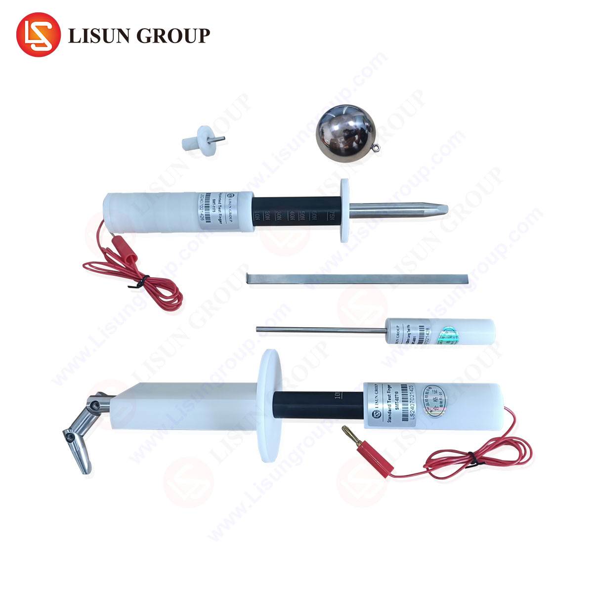
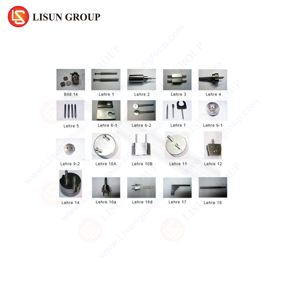
A comprehensive gauge set for CEE7 C13 validation typically comprises multiple instruments, each serving a distinct verification function. The primary gauges are the aforementioned dimensional check gauges (Gauge A and Gauge B). Constructed from hardened steel or similarly robust materials, they apply a defined force (e.g., 40N for plug gauges) to simulate real-world insertion and extraction stresses. Their critical dimensions—pin diameter, pin length, span between pins, and overall plug body profile—are machined to the extreme tolerances permitted by the standard. For socket-outlets, socket gauge A must not enter the aperture when a specified force is applied, while socket gauge B must enter fully under its own weight or a minimal force, ensuring the socket will accept a compliant plug.
Supplementary gauges address other safety clauses. The pin gauges verify the exact diameter of live and neutral pins. The check gauge for entry of pins assesses protection against finger contact with live parts, ensuring a test finger (as per IEC 61032) cannot touch hazardous components. The static load test appliance applies a weight to the plug body to evaluate the cord anchorage’s mechanical strength. Each gauge is, therefore, a physical embodiment of a specific safety requirement, transforming abstract dimensional drawings into a binary pass/fail outcome.
LISUN Gauges for Plugs and Sockets: Technical Specifications and Implementation
The LISUN Gauges for Plugs and Sockets product line represents a calibrated implementation of the IEC 60884-1 gauge requirements for various standards, including CEE7 C13. These instruments are engineered to provide laboratories, manufacturers, and certification bodies with reliable, traceable compliance verification.
Specifications and Construction: LISUN gauges are precision-machined from high-grade tool steel, heat-treated for wear resistance and long-term dimensional stability. Surfaces are finely finished to prevent binding during testing and to avoid damaging the product under test. Each gauge set is accompanied by a calibration certificate traceable to national metrology institutes, affirming its conformity to the reference dimensions stipulated in the standard. Key components of a CEE7 C13 set include the Plug Gauge A (max/min), Plug Gauge B (min/max), corresponding Socket Gauges A and B, pin diameter gauges, and the necessary force application apparatus.
Testing Principles and Operational Protocol: The testing sequence follows a logical, repeatable methodology. For a CEE7 C13 plug, the technician first verifies pin diameters using the go/no-go pin gauges. Subsequently, the plug is subjected to the Plug Gauge B test; the plug must not fit into the gauge, confirming it is not oversized. It is then tested with Plug Gauge A; it must fit completely into the gauge under the application of the specified force (e.g., 40N ± 2N), confirming it is not undersized. For a socket-outlet, Socket Gauge A must not enter, while Socket Gauge B must enter fully under its own weight or a minimal prescribed force. The LISUN system often integrates clear force indicators or calibrated weights to ensure the exact application of mandated forces, eliminating operator-induced variance.
Industry Applications and Quality Assurance Integration
The application of plug and socket gauges permeates multiple stages of the product lifecycle. In Research & Development, engineers use gauge sets to validate prototypes against target specifications before formal compliance testing. During mass production, gauges are deployed for incoming quality control (IQC) of components like pins and molded bodies, and for final random inspection (FRI) of finished goods. This frontline screening catches dimensional drift in injection molding tools or stamping processes before it results in a batch failure.
For third-party testing laboratories and certification bodies like TÜV, UL, or Intertek, LISUN and equivalent gauge sets are indispensable tools for conducting type tests. A product cannot receive a CB Scheme report or regional certification marks (CE, GS, etc.) without successfully passing all relevant gauge checks. Furthermore, in post-market surveillance, regulatory authorities use these same gauges to verify the continued compliance of products sourced from the market, providing objective evidence in cases of non-conformity.
Comparative Analysis: Manual Gauges vs. Automated Testing Systems
While manual gauge sets remain the definitive reference method, technological evolution has introduced automated plug and socket testers. A comparative analysis reveals distinct operational profiles. Manual gauges, such as the LISUN sets, offer uncompromising fidelity to the standard’s prescribed method. They are portable, require no power, have lower capital cost, and their mechanical operation is transparent and easily audited. Their limitation lies in throughput and potential for minor operator influence in force application.
Automated systems integrate gauges, force actuators, and sensors into a programmable unit. They offer high throughput, digital result logging, and eliminate operator variability. However, they represent a significantly higher capital investment and their internal calibration must itself be regularly verified against master gauges to ensure chain of traceability. In practice, a robust quality system often employs both: manual LISUN master gauges for periodic calibration of automated systems and for arbitration in borderline cases, and automated systems for high-volume production line testing. The LISUN gauges thus serve as the primary standard within the laboratory or factory metrology framework.
Metrological Considerations and Gauge Maintenance
The efficacy of any compliance verification system hinges on metrological integrity. Gauges are subject to wear, particularly from repeated testing of abrasive composite materials used in some plugs. Even minor wear on a gauge pin or contact surface can shift a product from a “pass” to a “fail” state, or worse, a “false pass.” A rigorous maintenance schedule is therefore imperative. This includes regular visual inspection for nicks or corrosion, periodic recalibration against a certified master set (typically annually, or per internal quality procedures), and proper storage in controlled environments to prevent rust or physical damage. The use of calibrated, certified gauge sets like those from LISUN provides a documented foundation for this traceability, which is a mandatory requirement for ISO/IEC 17025 accredited laboratories.
Economic and Safety Implications of Gauge-Based Compliance
The economic rationale for investment in precision gauging is compelling. The cost of a batch rejection during certification testing or a product recall due to non-compliant dimensions far exceeds the investment in a reliable gauge set. Furthermore, consistent gauge use reduces warranty claims related to poor fit, overheating from high contact resistance, or mechanical failure of the cord anchorage.
From a safety perspective, the role is fundamental. Correct pin spacing and size prevent arcing and overheating. Proper socket entry dimensions ensure shutters (where fitted) function correctly and that children cannot insert objects. Adequate plug body size and strength ensure the cord anchorage can withstand the rigors of use, preventing cable detachment and exposure of live conductors. In essence, each gauge test directly correlates to mitigating a specific electrical or mechanical hazard, making these tools critical components in the overall safety ecosystem.
FAQ Section
Q1: How frequently should our plug and socket gauges be recalibrated?
A1: Calibration intervals depend on usage frequency, material abrasiveness of tested products, and your quality system requirements. For active testing laboratories, annual recalibration is a common benchmark, traceable to a national metrology institute. Gauges used in high-volume production should be checked more frequently against a master set retained solely for calibration purposes.
Q2: Can one gauge set be used for multiple plug types, like CEE7 C13 and CEE7 C17?
A2: No. Each plug type defined by a standard has unique dimensional requirements. The CEE7 C13 (Europlug) and CEE7 C17 (French 2-pin) have different pin diameters, lengths, and body shapes. Using an incorrect gauge will yield invalid results. A dedicated gauge set, or a modular system with interchangeable gauge heads, is required for each standardized plug/socket type.
Q3: Our automated tester and a manual LISUN gauge give conflicting results for a socket-outlet. Which result takes precedence?
A3: The manual gauge, provided it is currently within its calibration period and applied according to the standard’s exact procedure (correct force, orientation), is the definitive reference. Automated systems should be programmed and calibrated to align with the manual gauge outcome. The conflict indicates a need to recalibrate the automated system’s actuators or sensors against the master manual gauge.
Q4: Beyond dimensional checks, what other tests are critical for CEE7 C13 plug compliance?
A4: Dimensional verification is foundational but not exhaustive. A full compliance test suite per IEC 60884-1 includes electrical tests (dielectric strength, insulation resistance, power dissipation), mechanical tests (cord anchorage pull, impact, pin rigidity), thermal tests (ball pressure, temperature rise), and material tests (glow-wire, flammability). Gauges address the critical first step of ensuring the product’s geometry is within safe limits.
Q5: What is the significance of the applied force (e.g., 40N) during plug gauge testing?
A5: The specified force simulates the maximum reasonable insertion force a user might apply. Testing under this force ensures that a plug which is at the extreme lower limit of dimensional tolerance will still make reliable electrical contact in a socket that is at the extreme upper limit of its tolerance. It validates the robustness of the interface under worst-case mechanical conditions.