


Comprehensive Guide to CEE7 C13 Plug and Socket Gauges: Principles, Standards, and Verification Methodologies
Introduction to the CEE7/13 Standard and Its Global Relevance
The CEE7/13 plug and socket system, commonly recognized as the “Schuko” (Schutzkontakt) standard, represents a cornerstone of electrical safety and interoperability across continental Europe and numerous other global markets. Characterized by its two 4.8 mm round pins for line and neutral, flanked by two grounding clips on the plug body that mate with socket side contacts, this design prioritizes user protection through reliable earthing before current-carrying pins establish connection. The widespread adoption of this system, governed by standards such as EN 50075 and national derivatives, necessitates rigorous dimensional and mechanical verification. This is where specialized plug and socket gauges become indispensable tools for manufacturers, testing laboratories, and certification bodies. These gauges are not mere measuring devices but are formalized acceptance instruments, whose dimensions are precisely derived from the maximum and minimum material conditions stipulated in the governing standards. Their application ensures that every manufactured plug can be safely inserted into any compliant socket, and vice versa, without compromising electrical contact integrity or user safety.
Fundamental Design Principles of Acceptance and Rejection Gauges
The verification philosophy for CEE7/13 components is bifurcated into two distinct but complementary gauge types: the “Go” (acceptance) gauge and the “No-Go” (rejection) gauge. This binary system provides a clear, unambiguous pass/fail criterion that transcends subjective measurement interpretation. The acceptance gauge is engineered to the maximum material limits for a socket outlet or the minimum material limits for a plug. For a socket gauge, this simulates the largest permissible plug that must still be insertable with a specified force, ensuring sockets are not manufactured too small. Conversely, the plug acceptance gauge simulates the smallest permissible socket aperture, verifying that a plug is not too large to enter a compliant socket. The rejection gauges apply the opposite logic. A socket rejection gauge, representing a plug at the minimum material condition plus a tolerance, must not fully enter a compliant socket, preventing sockets that are too loose and would offer inadequate pin grip. A plug rejection gauge, representing a socket at its maximum material condition minus a tolerance, must not fit over the plug, preventing plugs that are too small and could lead to poor contact or overheating. This principle of “maximum metal” and “minimum metal” condition verification is critical for ensuring interchangeability and safety across all production batches from all manufacturers.
Critical Dimensions and Tolerances Specified in CEE7/13
The dimensional integrity of the CEE7/13 interface hinges on several key parameters, each verified by specific gauge features. Pin diameter and spacing are paramount; the 4.8 mm pin diameter must be maintained within tight tolerances to ensure sufficient contact pressure within the socket’s contact tubes. Pin center-to-center distance, precisely defined at 19 mm, is equally critical to prevent misalignment or forced insertion. The grounding clip geometry—its width, thickness, profile, and location relative to the power pins—is a safety-critical feature that requires exact verification to guarantee earth continuity is established prior to the live contacts mating. Socket face profile dimensions, including the recess depth, the size and shape of the aperture for the plug body, and the location of the side earth contact slots, are all subject to gauge verification. Furthermore, mechanical tests such as the insertion/withdrawal force test, often conducted using a calibrated gauge and force meter, validate that the contact grip is sufficient for reliable operation but not excessive to hinder user connection. Each of these dimensions is not an ideal nominal value but a range, and the gauges embody the extremities of these ranges as defined by standards like EN 50075.
LISUN Gauges for Plugs and Sockets: A Technical Specification Overview
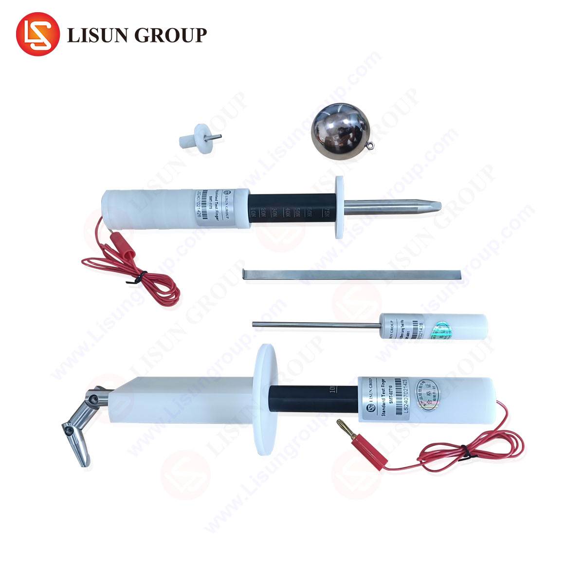
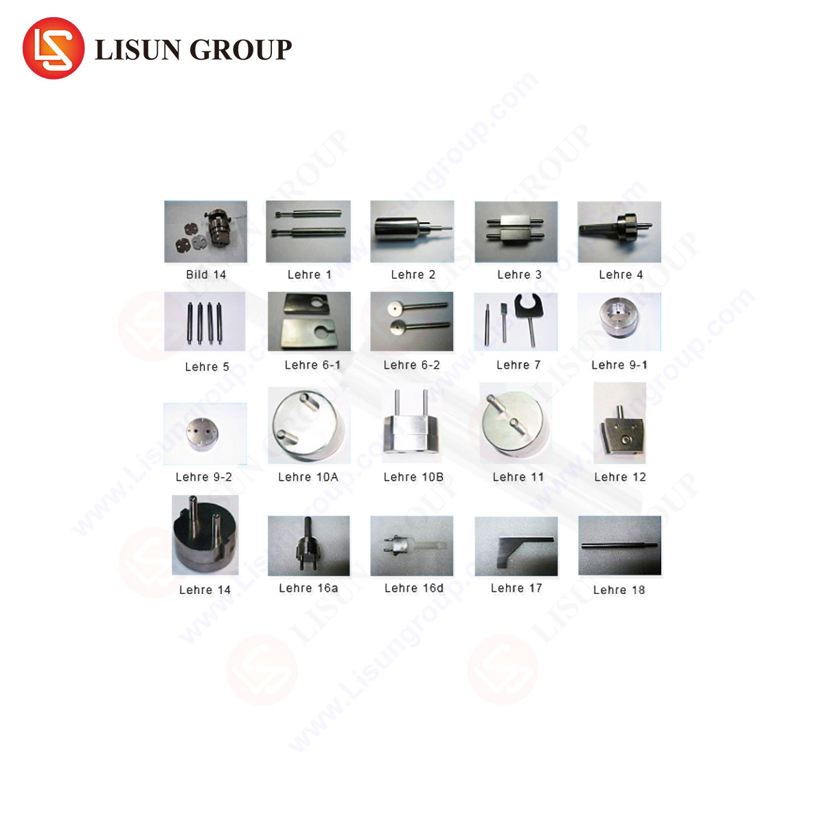
LISUN produces a comprehensive suite of gauges designed for the exacting verification of CEE7/13 components, aligning with international standards including IEC (International Electrotechnical Commission) and EN (European Norm). These instruments are manufactured from high-grade, dimensionally stable materials such as hardened steel or anodized aluminum to resist wear and environmental deformation, ensuring long-term calibration integrity. A typical LISUN CEE7/13 test kit encompasses multiple dedicated gauges, each serving a discrete verification function.
- Socket Outlet Gauge (Acceptance): This gauge replicates a plug at its maximum permissible dimensions. It features pins at the upper tolerance limit of 4.8 mm and incorporates the grounding clips at their maximum specified width and thickness. The gauge is applied with a defined test force (e.g., 40 N) to verify that a socket will accept a worst-case large plug without binding.
- Socket Outlet Gauge (Rejection): This gauge represents a plug at its minimum permissible dimensions. Its slenderer profile must not fully enter a compliant socket, confirming that the socket’s contact tubes provide adequate gripping force on a worst-case small plug.
- Plug Gauge (Acceptance): This device simulates a socket outlet at its minimum internal dimensions. A compliant plug must fit within this gauge, proving it is not oversized for the smallest permissible socket aperture.
- Plug Gauge (Rejection): Simulating a socket at its maximum internal dimensions, this gauge must not fit over a compliant plug, ensuring the plug is not undersized and will maintain sufficient contact pressure.
- Supplementary Gauges: Kits often include specialized tools for verifying pin length, grounding clip flexibility, socket recess depth, and aperture profile. A calibrated spring force gauge is typically integrated or supplied separately for measuring insertion and withdrawal forces.
The construction of these gauges involves precision machining and grinding, followed by meticulous quality control using coordinate measuring machines (CMMs) to certify their own dimensional accuracy traceable to national metrology institutes.
Operational Methodology and Testing Protocols in Manufacturing
In a production or quality assurance environment, the use of LISUN gauges follows a strict procedural protocol to eliminate operator variance. The process is typically non-electrical and purely mechanical. For socket testing, the acceptance gauge is carefully aligned with the socket face and a controlled force, measured via a push-pull gauge, is applied axially. A smooth, complete insertion within a specified force window constitutes a pass. Subsequently, the rejection gauge is attempted; its entry beyond a marked depth (usually indicated by a shoulder on the gauge) constitutes a failure. For plug testing, the plug is offered to the acceptance gauge; full entry without undue force is required. The rejection gauge must not encapsulate the plug’s contact pin assembly. These tests are often performed on a statistical sampling basis per production run (as per AQL, Acceptable Quality Level, schemes) or may be 100% verified for critical safety components. The gauges themselves are subject to a regular calibration schedule, typically annually, to account for potential wear, ensuring the continued validity of all test results derived from their use.
Industry Applications and Regulatory Compliance Imperatives
The primary application of CEE7/13 gauges is within the manufacturing ecosystem of plug and socket producers. Quality departments employ them for in-process checks, final product inspection, and failure analysis. Furthermore, independent testing laboratories and certification bodies (such as those granting the CE mark, GS mark, or TÜV certification) rely on these gauges as normative test equipment during type-testing and surveillance audits. Their verdict is often legally binding for market access. Beyond initial compliance, importers and large purchasers use these gauges for incoming inspection to verify that sourced products from various global suppliers meet the required specifications, mitigating liability and safety risks. The use of standardized, traceable gauges like those from LISUN is not merely a best practice but a fundamental requirement for demonstrating due diligence and conformity with the European Low Voltage Directive (LVD) 2014/35/EU and other regional safety frameworks.
Comparative Analysis: Manual Gauges Versus Automated Test Systems
While manual gauge kits represent the traditional and most widely accessible method of verification, technological advancement has led to the development of automated plug and socket test systems. These systems often integrate gauge fixtures with servo motors, precision load cells, and data acquisition software. LISUN provides solutions across this spectrum. Manual gauges offer unparalleled portability, lower capital cost, and simplicity for spot-checking on the factory floor or in a field audit. Automated systems, conversely, provide superior repeatability by eliminating operator influence, generate detailed quantitative data logs (e.g., exact insertion force curves), and significantly increase throughput for high-volume production lines. The choice between methodologies depends on the specific use case: manual gauges are ideal for audit compliance and flexible QA stations, while automated systems are optimized for integrated, high-speed production line testing and advanced laboratory analysis requiring detailed documentation.
Material Science and Metrological Considerations in Gauge Longevity
The enduring accuracy of a plug and socket gauge is a function of its material properties and manufacturing pedigree. Gauges subjected to repeated insertion cycles against spring-loaded contacts experience abrasive wear. LISUN gauges are typically fabricated from tool steel, hardened and tempered to a high Rockwell C hardness, or from premium aluminum alloys with a hard anodized surface. These materials provide exceptional resistance to deformation and scratching. Furthermore, the surface finish is critically controlled; a smooth, low-friction finish is necessary to prevent the gauge itself from damaging the product under test while ensuring that measured forces are representative of actual use. Metrological traceability, maintained through calibration certificates issued by accredited laboratories, is the final link in the chain of trust. This ensures that the gauge dimensions are themselves verified against a primary standard, making the entire testing process defensible in regulatory and commercial contexts.
FAQ Section
Q1: How frequently should LISUN CEE7/13 gauges be recalibrated?
A1: Calibration interval depends on usage frequency and the quality control protocols of the organization. Under typical industrial use, an annual calibration cycle is recommended and is often required by accreditation bodies (e.g., ISO/IEC 17025). High-volume production environments may necessitate more frequent intervals, such as semi-annually, to ensure continued measurement integrity.
Q2: Can one set of gauges be used to test both 230V and 120V versions of the CEE7/13 form factor?
A2: The CEE7/13 standard defines mechanical dimensions, which are independent of voltage rating. Therefore, a single set of gauges designed to the EN 50075 standard is applicable for verifying the mechanical compatibility of both 230V (European) and 120V (regional variants, where used) plugs and sockets of this type, provided they claim compliance to the same dimensional standard.
Q3: What is the consequence of a socket passing the acceptance gauge but failing the rejection gauge test?
A3: This is the intended and required outcome. A compliant socket must accept the (larger) acceptance gauge and must reject the (smaller) rejection gauge. If a socket were to accept both, it would indicate that its contact tubes are excessively wide, leading to insufficient grip on a minimum-sized plug—a potential fire hazard due to high-resistance contact.
Q4: Do LISUN gauge kits account for the testing of shutters in child-safe socket outlets?
A4: Standard dimensional gauge kits focus on the primary plug-socket interface. The testing of shutter mechanisms, as required by standards like EN 50075, typically involves separate, specialized test probes (e.g., standardized test pins of specific diameters and sequencing) to verify shutter resistance and operation. These are often available as complementary accessories within a full compliance test suite.
Q5: How does temperature and humidity affect gauge measurements and testing?
A5: Gauges manufactured from thermally stable materials exhibit minimal dimensional change within normal laboratory and factory environments. However, both gauges and the products under test should be acclimatized to a standard ambient temperature (e.g., 23°C ±5°C as per many standards) to ensure consistent results, particularly for precise force measurements. Humidity primarily poses a risk of corrosion; the hardened or anodized surfaces of quality gauges provide robust protection against this.