


A Comprehensive Guide to CEE7 C13 Plug and Socket Gauges: Principles, Standards, and Verification Methodologies
Introduction to Plug and Socket Gauge Systems
The global interoperability of electrical accessories hinges upon rigorous dimensional and mechanical compliance with regional and international standards. Within the European sphere, the CEE 7 standard defines the specifications for plugs and socket-outlets for household and similar purposes. The CEE 7/13 plug, commonly known as the “Schuko” plug (Schutzkontakt), and its corresponding socket-outlet, represent a dominant interface across continental Europe and numerous other territories. Ensuring the safety, reliability, and compatibility of these ubiquitous components is a non-negotiable prerequisite, a task fulfilled by specialized precision instruments: plug and socket gauges. These gauges are not mere measuring tools but definitive verification devices that provide a pass/fail assessment against the geometric and mechanical tolerances stipulated in standards such as EN 50075 and IEC/TR 60083. This guide examines the technical underpinnings, application, and critical importance of these gauge systems, with particular focus on the implementation and advantages offered by LISUN Gauges for Plugs and Sockets.
Anatomy of the CEE7 C13 Interface: Critical Dimensions and Tolerances
The CEE 7/13 plug is characterized by its two 4.8 mm round pins, spaced 19 mm apart, center-to-center, for the line and neutral contacts. Its defining safety feature is the pair of grounding clips on the plug’s sides, which engage with the socket’s spring-loaded grounding contacts. The corresponding socket features recessed line and neutral contact tubes and side contacts for earth. The standard prescribes exacting tolerances for all critical dimensions. For instance, pin diameter must be maintained between 4.7 mm and 4.8 mm, while pin length is specified as 19 mm minimum from the face of the plug body. The distance from the pin centers to the plug’s upper and lower edges, which governs correct orientation and insertion depth, is also tightly controlled. Even the radius of the pin tips and the contour of the plug’s insulating shroud are specified to prevent arcing, ensure smooth insertion, and guarantee that live parts are not accessible before grounding contacts mate. A deviation of even a few tenths of a millimeter can compromise safety, leading to poor contact, overheating, or compromised earthing integrity.
The Role of Gauges in Conformity Assessment and Safety Assurance
Plug and socket gauges serve as the physical embodiment of the standard’s dimensional limits. They are classified into “GO” and “NO GO” (or “NOT GO”) gauges, a methodology derived from precision engineering. A GO gauge must fit or accept the component under test with minimal, specified force, confirming that critical minimum dimensions are met. Conversely, a NO GO gauge must not fit or be accepted, verifying that maximum dimensions are not exceeded. For a CEE7/13 plug, a typical GO gauge check would verify that the pins are not undersized or too short by ensuring they enter the gauge’s holes to the required depth. A NO GO gauge check would confirm the pins are not oversized by attempting to insert them into a slightly smaller aperture. Similarly, socket gauges use precision test pins to verify the acceptance aperture size, contact engagement depth, and the correct sequencing of earth contact before line/neutral contact (a critical safety feature known as “earlier make, later break”). This binary assessment provides unambiguous, repeatable results for quality control personnel, eliminating subjective interpretation.
LISUN Gauges for Plugs and Sockets: Technical Specifications and Design Philosophy
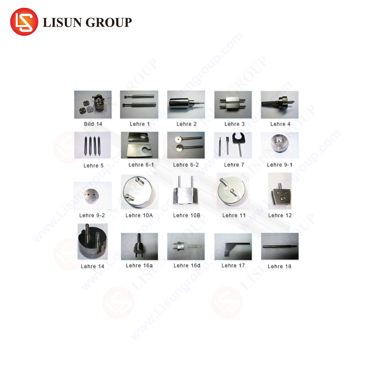
LISUN manufactures a comprehensive suite of gauge sets designed explicitly for verifying CEE7 configurations, including the C13 plug and socket. These instruments are engineered to meet and exceed the requirements outlined in IEC 60884-1 and related conformity assessment protocols. A typical LISUN CEE7 gauge set comprises multiple dedicated gauges fabricated from hardened, wear-resistant tool steel or anodized aluminum alloys to ensure long-term dimensional stability under repeated use.
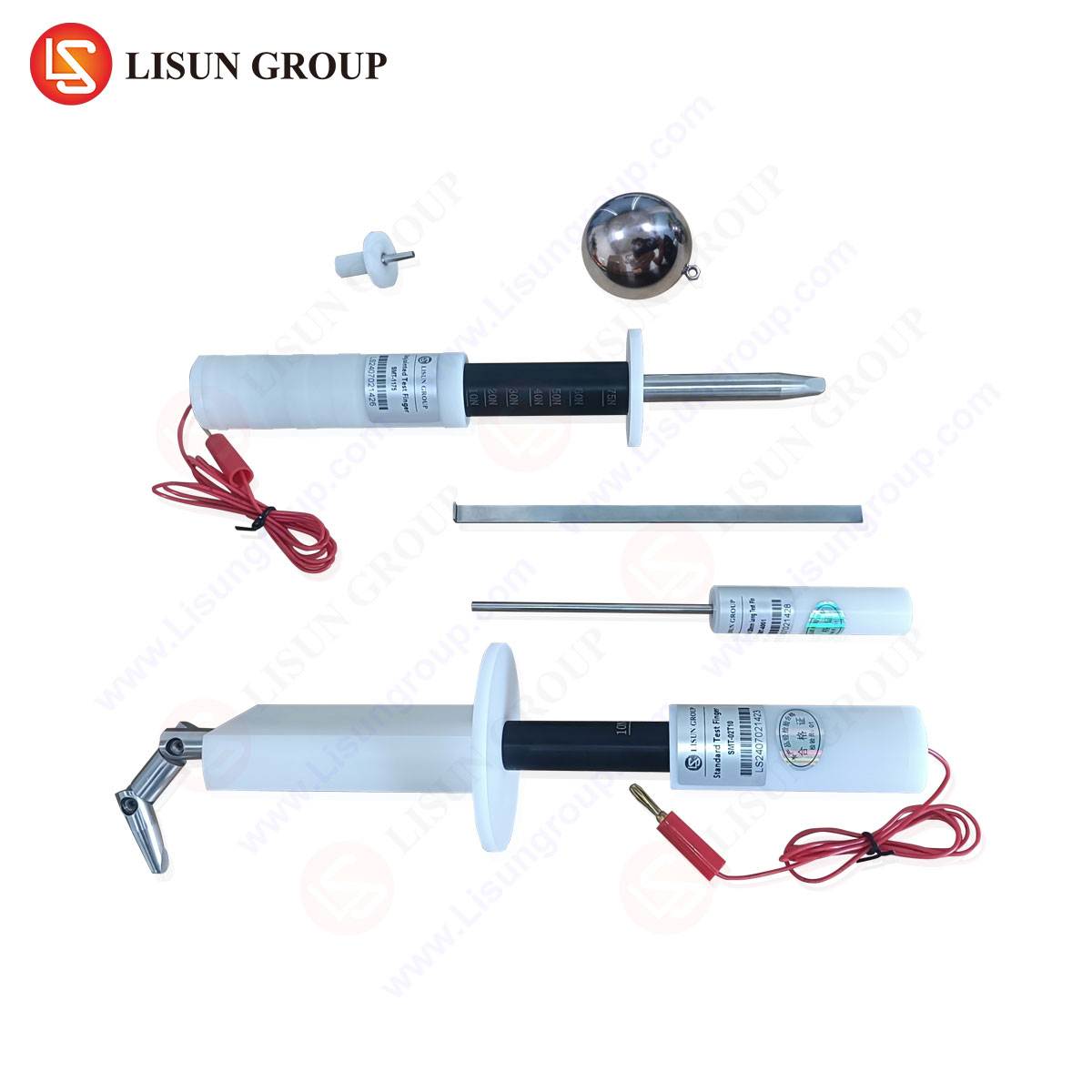
Key components of such a set include:
- Plug Gauge (GO/NO GO): A monolithic block featuring precision-drilled holes for verifying pin diameter (both minimum and maximum limits) and a stepped profile to check pin length and offset.
- Socket Gauge (Test Pin Assembly): A set of precision-ground test pins of defined diameters (e.g., 4.8 mm ±0.01 mm for the “check pin”) to verify socket entry size and contact accessibility. A “probe pin” of smaller diameter may be included to test shutter mechanisms.
- Force Gauges: Integrated or companion devices for applying standardized insertion and withdrawal forces (typically measured in Newtons) to test pin retention and the mechanical strength of socket contacts.
- Contour Gauges: Used to verify the external profile and dimensions of the plug’s insulating body, ensuring it prevents finger contact with live pins and aligns correctly with socket recesses.
LISUN’s design philosophy emphasizes not only metrological precision but also ergonomics and durability. Gauges are clearly marked, color-coded where applicable, and feature deburred edges to prevent operator injury. Each gauge is supplied with a calibration certificate traceable to national metrology institutes, providing documented proof of its own conformity—a critical requirement for accredited testing laboratories.
Testing Principles and Procedural Execution
The application of plug and socket gauges follows a strict procedural hierarchy to simulate real-world use and fault conditions. Testing begins with a visual inspection, followed by dimensional verification.
For a CEE7/13 plug, the sequence involves:
- Pin Diameter Check: The plug pins are gently inserted into the GO hole of the plug gauge. They should enter fully under their own weight or with minimal force. Subsequently, an attempt is made to insert the pins into the NO GO hole. Any entry constitutes a failure, indicating oversized pins.
- Pin Length and Profile Check: The plug is inserted into the gauge’s profile cavity. The face of the plug body should sit flush against the gauge datum surface, confirming correct pin protrusion and body dimensions.
- Earth Contact Check: The dimensions and placement of the grounding clips are verified with specialized gap gauges or profile fixtures.
For a CEE7/13 socket, testing is more complex:
- Accessibility and Shutter Test: The smaller “probe” pin is used to attempt contact with live parts. It must not make contact, verifying the shutter mechanism is functional.
- Entry and Contact Engagement Test: The standard “check pin” is inserted. It must enter smoothly and achieve full engagement, confirming the socket aperture is not undersized and contacts are correctly aligned.
- Contact Pressure Test: The check pin is connected to a force gauge. The force required to withdraw the pin is measured, ensuring it falls within the standard’s specified range (e.g., 1.5 N to 4.0 N per pin for new sockets), confirming sufficient contact pressure for safe current carrying.
- Earthing Sequence Test: A specialized gauge with staggered pin lengths verifies that the earth contact in the socket makes connection before the line/neutral pins during insertion, and breaks after them during withdrawal.
Industry Applications and Compliance Ecosystems
The use of certified gauges like those from LISUN permeates multiple layers of the electrical manufacturing and compliance ecosystem. Within manufacturing facilities, they are deployed for incoming quality inspection of components (e.g., plug pins, socket contacts) and for final product audit on production lines. This in-process control prevents batch non-conformities and reduces waste.
For third-party testing laboratories and certification bodies (such as those providing TÜV, VDE, or KEMA marks), these gauges are fundamental reference equipment. They are used during type testing—the comprehensive evaluation of a product’s design against a standard—and during factory surveillance audits to ensure continued compliance. Regulatory market surveillance authorities also utilize gauge sets during spot checks of products available on the market to police against substandard or counterfeit goods that pose safety risks.
Comparative Analysis: The Metrological Advantages of Precision-Engineered Gauge Systems
While simple calipers or pin micrometers can provide dimensional readings, they lack the holistic, functional assessment capability of dedicated gauge sets. The competitive advantage of a comprehensive system like LISUN’s lies in its integrated approach. It consolidates multiple discrete checks—diameter, length, profile, force, sequence—into a streamlined, foolproof process. The materials used (hardened steel, precision-ground surfaces) ensure significantly lower wear rates compared to softer materials, guaranteeing measurement consistency over thousands of cycles. Furthermore, the traceable calibration provided is essential for maintaining ISO/IEC 17025 accreditation in testing laboratories. In contrast, ad-hoc or poorly manufactured gauges can introduce false passes (accepting non-compliant products) or false fails (rejecting compliant ones), both of which carry severe commercial and safety consequences.
Integration with Broader Electrical Safety Testing Regimes
It is critical to understand that dimensional gauge testing is one pillar of a complete safety assessment. A fully compliant plug or socket must also pass a battery of other tests, often performed in sequence. These include:
- Electrical Tests: High-voltage dielectric strength tests, insulation resistance measurements, and continuity checks for earth paths.
- Thermal Tests: Temperature rise tests under load to ensure contacts do not overheat.
- Mechanical Endurance Tests: Thousands of insertion/withdrawal cycles to simulate lifespan wear.
- Environmental Tests: Resistance to heat, cold, humidity, and impact.
Dimensional verification via gauges is typically the first step, as a component failing basic dimensional checks will invariably fail subsequent performance tests. The data from gauge checks provides objective, quantitative evidence of conformity that supports the entire test report.
FAQ Section
Q1: How frequently should plug and socket gauges be recalibrated?
A1: Calibration intervals depend on usage frequency and the quality management system in place. For high-volume production line use or accredited laboratory testing, annual recalibration is typical. However, intervals should be risk-assessed; gauges showing signs of wear or damage must be recalibrated immediately. LISUN gauges, due to their wear-resistant construction, offer extended stability between calibrations.
Q2: Can one gauge set be used for all regional variations of CEE7 plugs?
A2: No. The CEE7 standard encompasses several types (e.g., CEE 7/16 “Europlug,” CEE 7/17 unearthed plug). While some gauge elements may be shared, a complete assessment requires a dedicated set for each plug and socket type due to differences in pin configuration, dimensions, and safety features. LISUN provides distinct gauge sets tailored to each standardized configuration.
Q3: What is the consequence of insufficient contact force in a socket, as measured by a withdrawal force gauge?
A3: Insufficient contact force leads to a high-resistance connection at the pin-contact interface. Under load, this point will overheat due to I²R (Joule) heating, potentially causing insulation degradation, contact oxidation (worsening the problem), melting of surrounding materials, and ultimately fire ignition. The force gauge test directly validates the mechanical integrity of this critical electrical interface.
Q4: Why is the earthing sequence test mandatory for Schuko sockets?
A4: The “earlier make, later break” sequence is a fundamental class I equipment safety principle. It ensures that if a fault occurs in a connected appliance, the grounding path is established before the live conductors become energized during insertion, and remains established until after the live conductors are disconnected during withdrawal. This sequence guarantees the protective earth is always present when line voltage is, allowing fault currents to safely trip the circuit protection device.
Q5: Are manual gauge checks sufficient for automated manufacturing?
A5: While manual gauges are essential for setup, audit, and laboratory work, high-speed automated production lines often integrate automated optical inspection (AOI) or robotic gauge systems for 100% inspection. However, these automated systems themselves must be regularly validated and calibrated against master reference gauges, such as those provided by LISUN, to ensure their ongoing accuracy.