


A Comprehensive Guide to CEE7 C15 Test Gauges: Principles, Applications, and Instrumentation
Introduction to Dimensional Verification in Plug and Socket Systems
The global interoperability of electrical plugs and sockets hinges upon precise mechanical conformity to established standards. Dimensional deviations, however minor, can compromise electrical safety, leading to poor contact, overheating, arcing, or insecure mechanical engagement. The CEE7 standard, governing the dimensional and electrical requirements for plugs and socket-outlets used across much of Europe and other regions, mandates rigorous verification. Within this framework, CEE7 C15 test gauges serve as the definitive metrological instruments for validating the critical internal geometry of socket-outlets designed to accept Type C (Europlug) and Type E/F (French/German Schuko) plugs. These gauges are not mere templates but calibrated artifacts whose application forms a non-negotiable step in the manufacturing quality control process, third-party certification, and market surveillance activities.
Anatomy and Functional Specifications of the CEE7 C15 Gauge
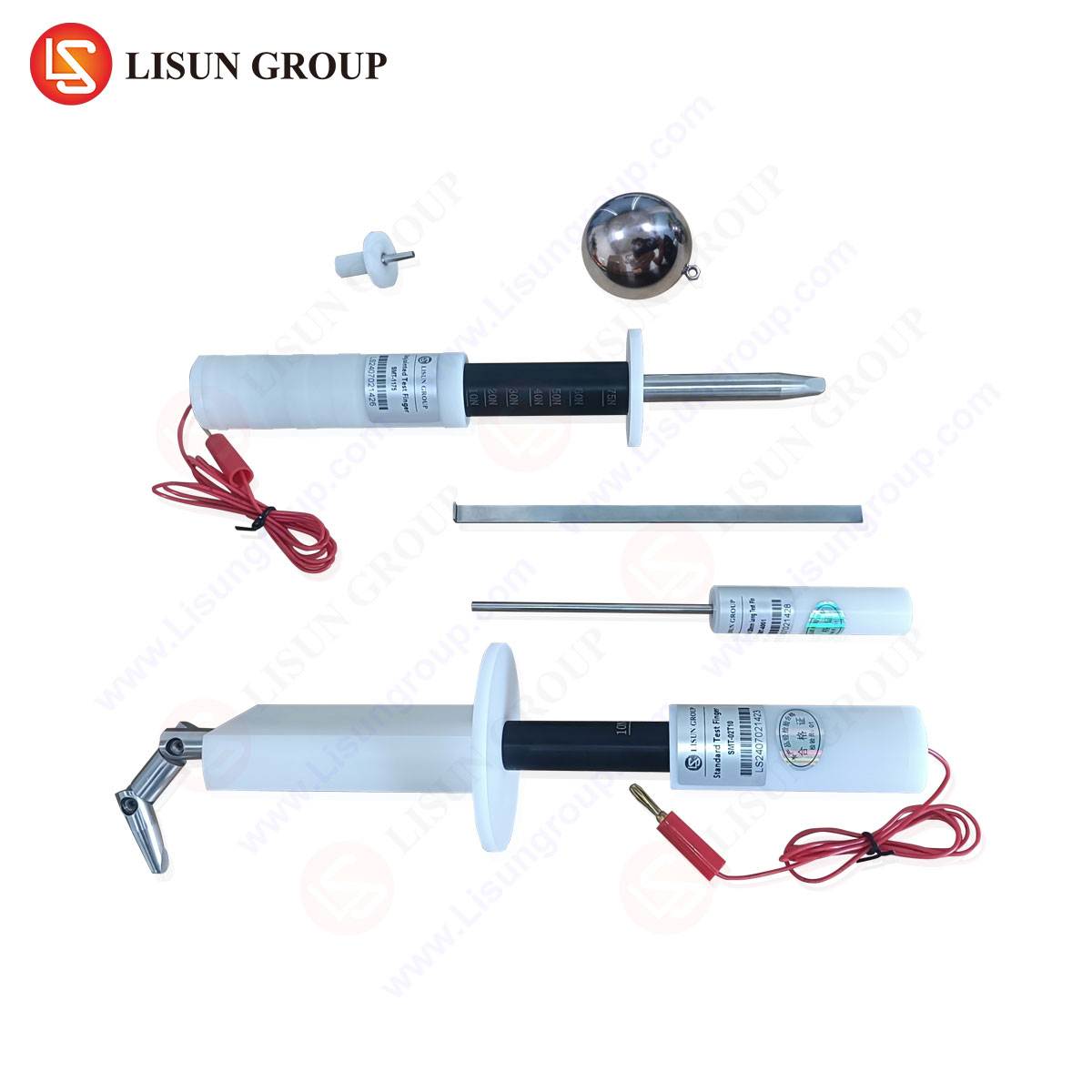
The CEE7 C15 gauge is a passive, non-electrical tool machined to exacting tolerances as specified in the standard’s relevant sheets. Its primary function is to assess the socket-outlet’s contact tube receptacles, earth contact arrangements, and the overall entry aperture. The gauge typically consists of a main body representing the plug’s pin configuration—two cylindrical probes for phase and neutral contacts and a distinct earth contact probe or surface—mounted on a handle. Critical dimensions include the diameter, length, and spacing of the contact probes, which are machined to the maximum permissible plug pin dimensions. This “worst-case” simulation ensures that any socket-outlet accepting the gauge will also accept any compliant plug within the standard’s specified manufacturing tolerances.
A secondary, and equally vital, function is the “no-go” test. Certain gauges, or specific facets of a single gauge, are designed to the minimum socket dimensions. These elements must not fully enter a compliant socket, thereby verifying that the socket contact tubes possess sufficient spring tension to grip standard plugs securely. The application of specified insertion and withdrawal forces, measured via a spring balance or force gauge attached to the test instrument, completes the quantitative assessment. This dual go/no-go methodology provides a binary yet scientifically grounded pass/fail criterion for socket geometry.
The Metrological Foundation of Gauge-Based Socket Verification
The testing principle is rooted in geometric dimensioning and tolerancing (GD&T). The socket-outlet is a featured hole pattern whose functional acceptance is defined by its virtual condition—the boundary established by the collective effects of size, form, and orientation tolerances. The C15 test gauge embodies this virtual condition for the mating plug. When the gauge inserts smoothly under its own weight or a minimal force (as per the standard), it confirms that the socket’s internal features do not infringe upon this boundary.
The verification of contact tube engagement force introduces a tribological and mechanical component. The measured withdrawal force correlates directly with the normal force exerted by the contact tube’s spring mechanism on the plug pin. This force is a critical determinant of electrical contact resistance; insufficient force leads to high-resistance connections and potential overheating. The test gauge, by presenting a standardized, hardened surface of known geometry and finish, allows for the repeatable measurement of this engagement force, isolating the socket’s performance from variables inherent in using actual production plugs.
LISUN Gauges for Plugs and Sockets: Engineered for Conformity Assessment
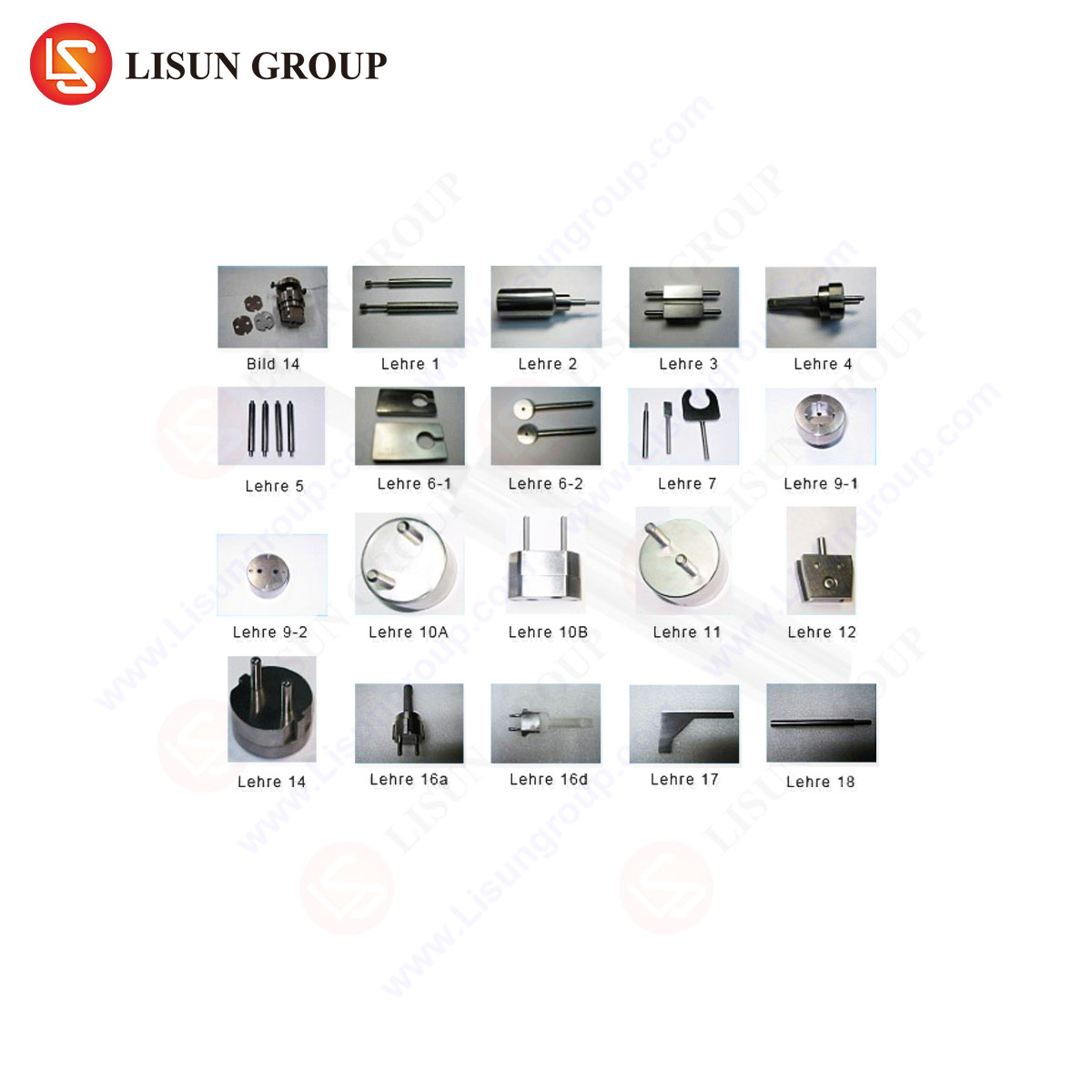
Within the landscape of test equipment manufacturers, LISUN produces a suite of gauges for plugs and sockets engineered to meet the exacting requirements of international standards, including the CEE7 series. The LISUN CEE7 C15 test gauge set is manufactured from hardened tool steel or equivalent durable materials to resist wear and maintain calibration integrity over thousands of insertion cycles. Each gauge is subject to post-machining dimensional verification using coordinate measuring machines (CMMs) to ensure compliance with the normative dimensions outlined in standards such as EN 50075 and EN 50079.
The LISUN design incorporates features for practical laboratory and production line use. Handles are ergonomically shaped and may include integrated attachment points for calibrated force measurement devices. The gauges are often supplied as a matched set, including both the “go” gauge (CEE7 C15) and the essential “no-go” elements, presented in a protective case with certified calibration documentation traceable to national metrology institutes. This traceability is not an ancillary feature but a foundational requirement for any testing performed in support of IECEE CB Scheme certifications or other accredited conformity assessments.
Industry Applications: From R&D to Market Surveillance
The application of CEE7 C15 gauges spans the entire product lifecycle. In the Research & Development phase, engineers use these gauges to verify prototype mold tools and socket designs before committing to mass production. During manufacturing, they are deployed for first-article inspection and periodic statistical process control (SPC) checks on injection-molded socket bodies and stamped contact assemblies. A common sampling plan might require gauge testing every four hours on a production line, with data logged to monitor for tool wear or press misalignment.
For third-party testing laboratories and certification bodies (e.g., UL, TÜV, Intertek), the gauge is a mandatory piece of equipment for type testing. No socket-outlet can receive a CE mark or equivalent certification without successfully passing the C15 gauge test protocol. Finally, market surveillance authorities utilize these same gauges in post-market audits to verify that products continuing to circulate in the marketplace retain compliance with the originally certified design, guarding against quality fade or unauthorized design modifications.
Comparative Analysis: Gauges Versus Coordinate Measuring Machines
A relevant technical discussion involves the role of traditional test gauges versus modern multi-sensor coordinate measuring machines. While a CMM can provide a comprehensive volumetric analysis of a socket’s internal geometry, generating a detailed point cloud and deviation map, the process is slow, requires skilled operation, and is sensitive to the CMM probe’s access and deflection within small cavities. The CEE7 C15 gauge, in contrast, provides a functional test—a direct simulation of the mating part’s function. It answers the primary question: Will a compliant plug fit and be held securely? Its speed, simplicity, and direct correlation to the standard’s pass/fail criteria make it indispensable for high-volume verification. The most rigorous quality regimes often employ both: CMMs for initial tool qualification and annual audits, and test gauges for daily production control.
Maintaining Gauge Integrity and Calibration Protocols
The accuracy of the testing regime is entirely dependent on the integrity of the gauge itself. Wear, particularly on the leading edges of the contact probes and the earth engagement surfaces, will gradually alter the effective dimensions, potentially causing the acceptance of non-conforming sockets (a Type II error). A formal calibration schedule is therefore imperative. Recommended practice involves annual recalibration for gauges in regular use, with interim checks using a reference master socket or ring gauges. Storage in a controlled environment, protection from impact, and cleaning after use to remove insulating debris or lubricants are essential maintenance procedures to prevent false readings.
Integration into Automated Test Rigs and Smart Manufacturing
The evolution towards Industry 4.0 has seen the integration of passive test gauges into automated test stations. In these systems, a robotic arm manipulates the CEE7 C15 gauge, with integrated load cells and linear variable differential transformers (LVDTs) measuring insertion force, withdrawal force, and depth of penetration with high precision. The data is automatically recorded to a statistical database, enabling real-time trend analysis and predictive maintenance alerts for production machinery. LISUN and similar manufacturers now offer gauges designed with such integration in mind, featuring flat mounting surfaces, standardized mechanical interfaces, and material choices optimized for consistent performance with automated handling systems.
Conclusion: The Unwavering Role of Physical Gauge Verification
Despite advancements in optical and tactile scanning technologies, the CEE7 C15 test gauge remains a cornerstone of socket-outlet safety verification. Its elegance lies in its direct functional replication of the plug-socket interface, providing unambiguous, standards-defined results. For manufacturers, certification bodies, and regulators, it is a tool of compliance, safety, and interoperability. As plug and socket designs evolve to accommodate new materials and smart grid functionalities, the fundamental requirement for dimensional conformity—ensured by instruments like the LISUN CEE7 C15 gauge set—will persist as a primary safeguard in electrical product safety.
FAQ Section
Q1: How frequently should a CEE7 C15 test gauge be recalibrated in an active production environment?
A1: Calibration intervals should be risk-based. For gauges in daily use on a production line, an annual recalibration by an accredited laboratory is a standard minimum. However, if the gauge is used for high-frequency testing (e.g., hundreds of insertions per day), a six-month interval or the use of a weekly check gauge against a master reference socket is recommended to detect premature wear.
Q2: Can a single CEE7 C15 gauge test both 2-pin (Type C) and 3-pin (Type E/F) socket-outlets?
A2: The standard CEE7 C15 gauge is designed primarily for the 3-pin (Schuko/French) socket, incorporating earth contacts. To test a socket designed only for 2-pin Europlugs (Type C), which lacks earth contact tubes, a different or modified gauge without the earth probe is required, as the presence of an earth probe would constitute a no-go condition for the simpler socket design.
Q3: What is the consequence of a socket passing the “go” test but failing the “no-go” test?
A3: This indicates a potential safety issue. Passing the “go” test confirms plug compatibility. Failing the “no-go” test suggests the socket’s contact tubes are too large or lack sufficient spring tension. This could result in a loose connection with a standard plug, leading to high electrical contact resistance, overheating, and a fire risk. The socket would be deemed non-compliant.
Q4: In automated testing, how is the specified withdrawal force measured accurately?
A4: Automated test stations use a precision load cell or force transducer integrated into the gauge’s actuation mechanism. The gauge is inserted, then withdrawn at a controlled, constant speed (e.g., 50 mm/min as per some standards). The force transducer records the peak force required to disengage the gauge from the socket’s contact tubes, providing a digital readout that is more repeatable than manual spring balance methods.
Q5: Why are materials like hardened tool steel specified for high-quality gauges like those from LISUN?
A5: Socket contact tubes are typically made of spring-tempered brass or phosphor bronze, which are relatively soft metals. Repeated testing with a gauge made from a softer material would cause the gauge itself to wear down, effectively changing its calibrated dimensions and leading to false approvals. Hardened tool steel provides the necessary wear resistance to maintain dimensional stability over a long service life, ensuring measurement integrity.