


A Comprehensive Guide to CEE7 C18 Connector Gauges: Principles, Standards, and Verification Methodologies
Introduction to CEE7 C18 Connector Gauges
The CEE7 C18 connector gauge represents a critical instrument within the quality assurance and compliance verification processes for the global electrical accessories industry. Specifically designed to assess the dimensional conformity of plugs and sockets conforming to the CEE 7/17 specification—commonly known as the “Europlug” and its corresponding socket-outlets—these gauges serve as an unambiguous arbiter between acceptable and non-compliant components. Their function transcends simple measurement; they provide a definitive, standards-based judgment on whether a plug can be safely inserted, engaged, and withdrawn from a socket, thereby ensuring fundamental electrical safety and mechanical interoperability. The proliferation of the non-polarized, two-pole Europlug across continental Europe and other regions necessitates rigorous manufacturing control, for which specialized gauge systems are indispensable. This guide delineates the technical specifications, operational principles, and application protocols governing CEE7 C18 gauges, with particular emphasis on advanced testing solutions such as those developed by LISUN Gauges for Plugs and Sockets.
Deconstructing the CEE 7/17 Standard: Dimensional Tolerances and Safety Imperatives
To comprehend the gauge’s design, one must first understand the standard it enforces. The CEE 7/17 specification (now largely integrated into IEC/TR 60083) defines a two-pole plug with rounded, parallel pins of 4.0 mm diameter, 19.0 mm length, and spaced 19.0 mm between centers. The plug body is characterized by its tapered, rounded shape, which facilitates insertion into a variety of socket types (CEE 7/1, 7/3, 7/5, 7/7). The permissible dimensional tolerances are precisely defined, typically within ±0.05 mm to ±0.1 mm for critical pin dimensions. The socket-outlet, conversely, must accept this plug reliably while rejecting larger or incorrectly configured pins. The CEE7 C18 gauge is engineered to verify the socket’s acceptance aperture and contact geometry. It consists of two primary elements: a “GO” gauge, which must insert fully and correctly to confirm minimum required dimensions, and a “NO GO” gauge (or set of gauges), which must be rejected to confirm maximum permissible dimensions and safety features like shutters are functioning. This binary pass/fail methodology eliminates subjective interpretation, providing a clear compliance check.
Anatomy and Functional Taxonomy of CEE7 C18 Gauge Systems
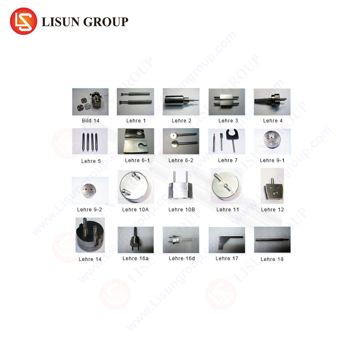
A comprehensive CEE7 C18 gauge kit is not a singular tool but a system of precision-machined components, each serving a distinct verification function. The system typically includes:
- Socket Gauge (C18 Body): This is the primary “GO” gauge. It mimics the maximum allowable dimensions of a compliant Europlug. Successful, unaided insertion and withdrawal of this gauge into a socket-outlet verifies that the socket’s entry aperture, contact spacing, and depth are sufficient to accept a standard plug. Its construction from hardened steel or durable polymer ensures minimal wear over thousands of cycles.
- Pin Gauges (Supplementary “NO GO” Elements): These are individual pin or pin-pair gauges designed to test specific rejection criteria. Examples include oversize diameter pins (e.g., 4.8 mm) that must not be inserted to verify contact resilience and shutter strength, and undersize or misaligned pin sets that test for improper engagement. Some systems include a “test pin” to individually check shutter operation on one side of the socket.
- Force Application Mechanisms: Critical to the test’s validity is the application of a standardized force. Gauges may incorporate spring-loaded mechanisms or be used in conjunction with calibrated force gauges to apply the exact force specified in the standard (e.g., 40 N for insertion, 20 N for lateral misalignment tests). This ensures the test simulates real-world use and not an artificially high insertion pressure.
The Metrological Foundation: Calibration Traceability and Uncertainty Management
The authority of any CEE7 C18 gauge derives from its traceable calibration to international standards of length (SI meter). Manufacturers of high-grade gauges, such as LISUN, maintain a rigorous calibration chain. Master gauges are calibrated against reference standards in accredited laboratories, and working gauges are subsequently verified against these masters. This process ensures that the gauge’s dimensions are not merely “approximately correct” but are certifiably within a defined and minuscule uncertainty envelope, often on the order of micrometers. The calibration certificate, detailing actual measured dimensions and associated uncertainties, is a mandatory document for laboratories operating under ISO/IEC 17025 accreditation. Without this traceability, compliance declarations hold no legal or technical weight in regulated markets.
LISUN Gauges for Plugs and Sockets: A Case Study in Integrated Verification
The LISUN CEE7 C18 gauge system exemplifies the integration of precision metrology with practical testing ergonomics. Designed for use in R&D laboratories, quality control checkpoints, and certification body facilities, the system addresses the full spectrum of verification required by the standard.
Specifications and Design Philosophy: LISUN’s gauge sets are typically machined from hardened tool steel or anodized aluminum alloys, providing an optimal balance of dimensional stability, wear resistance, and corrosion protection. Each gauge element is clearly marked with its function (e.g., “GO,” “NO GO 4.8mm”). The system is often housed in a custom foam-lined case, protecting the gauges from damage and contamination. Crucially, LISUN designs its gauges to be used in conjunction with its own or universal force measurement devices, ensuring the applied test parameters are quantifiable and repeatable.
Testing Principles in Practice: The LISUN system operationalizes the standard’s clauses. For socket testing, the procedure is systematic:
- Visual Inspection: Check for obvious defects.
- “GO” Gauge Test: Insert the C18 socket gauge with a specified force (e.g., 40 N). It must enter fully and seat properly without binding.
- Shutter Operation Test: Using a single test pin, verify that shutters (if present) operate independently and do not allow access to live parts when only one side is engaged.
- “NO GO” Gauge Tests: Attempt to insert the oversize pin gauges with a limited force (e.g., 20 N). The socket must reliably reject these gauges. Similar tests with misaligned pin pairs check for improper engagement paths.
Industry Use Cases and Application: The primary application is in manufacturing quality assurance. Production line samples are subjected to gauge tests at defined intervals to catch tooling wear or assembly drift before non-conforming products are batch-produced. Certification bodies like TÜV, UL, or Intertek use these gauges during type-testing and follow-up surveillance audits to grant or maintain safety marks (GS, CE, etc.). Furthermore, import regulators utilize them at ports of entry for spot-checking shipments, preventing unsafe products from entering the supply chain.
Competitive Advantages of the LISUN Approach: LISUN’s systems distinguish themselves through several key attributes. First is comprehensive documentation, including detailed calibration certificates traceable to national metrology institutes. Second is ergonomic design, with gauges shaped to be easily handled and used in repetitive testing environments without sacrificing precision. Third is system completeness, offering not just the basic gauges but all necessary supplementary pins and recommended force measurement tools as a coordinated kit. Finally, material science plays a role; the selected alloys and hardening processes extend service life, reducing long-term cost and calibration frequency for high-volume users.
Interoperability with Complementary Testing Regimes
The CEE7 C18 gauge does not operate in isolation. It is a component of a broader product verification suite. A fully compliant CEE 7/17 plug or socket must also pass electrical tests (dielectric strength, insulation resistance, contact resistance), mechanical endurance tests (insertion/withdrawal cycles), and thermal tests (temperature rise under load). The dimensional gauge provides the foundational check; if a component fails the gauge test, subsequent electrical safety tests may be moot, as the product cannot ensure reliable contact or safe user interaction. Therefore, the gauge is often the first, and most critical, check in a testing sequence.
Common Non-Conformities Identified by Gauge Testing
Routine gauge application reveals typical manufacturing flaws. For sockets, these include: undersized entry apertures due to molding flash or deformation; incorrect contact alignment causing binding during “GO” gauge insertion; and faulty shutters that either fail to open with the correct force or fail to block the “NO GO” probes. For plugs, common issues are pin diameter exceeding maximum tolerance due to plating over-thickness or machining error, and incorrect pin center spacing causing difficult insertion or poor contact alignment. The gauge provides immediate, unambiguous feedback on these faults, enabling rapid corrective action.
FAQ Section
Q1: How frequently should a CEE7 C18 gauge set be recalibrated?
A1: Calibration interval depends on usage frequency, material wear, and quality system requirements. For high-volume testing in an accredited lab, annual recalibration is typical. Manufacturers like LISUN provide recommendations based on material specifications. The gauge should also be inspected visually for damage before each use.
Q2: Can a single gauge set be used to test both plugs and sockets?
A2: The core CEE7 C18 gauge is primarily for sockets. Testing plugs requires a different set of gauges, typically “pin gauge” sets for measuring plug pin diameter, length, and spacing against go/no-go limits, and a separate socket template to check plug body contour. A complete laboratory requires both plug and socket gauge families.
Q3: What is the consequence of using a worn or uncalibrated gauge?
A3: Using a non-conforming gauge invalidates all test results. A worn “GO” gauge may reject conforming products (a false fail), costing time and money in unnecessary rework. A worn “NO GO” gauge may accept non-compliant, potentially dangerous products (a false pass), creating liability and safety risks. Traceable calibration is a non-negotiable requirement.
Q4: Do CEE7 C18 gauges account for the force required to open socket shutters?
A4: The basic dimensional gauge does not measure shutter opening force. This is a separate test specified in standards like IEC 60884-1, performed with a specialized force gauge and test pin. However, a comprehensive gauge kit, such as those from LISUN, will include the recommended test pin to perform this check in conjunction with a force measurement device.
Q5: Are there environmental conditions that can affect gauge accuracy?
A5: Yes. As with all precision dimensional tools, temperature is the primary factor. Standards typically specify a reference temperature (e.g., 20°C ± 2°C) for testing. Significant deviations can cause thermal expansion or contraction of both the gauge and the device under test, leading to measurement error. Gauges and products should be acclimatized to a stable laboratory environment before testing.