


Comprehensive Guide to the 0.5mm Test Wire Probe: Principles, Applications, and Standards Compliance
Introduction to Access Probe Verification in Product Safety Testing
The verification of product safety, particularly concerning the prevention of electric shock and fire hazards, is a foundational requirement across global manufacturing sectors. A critical aspect of this verification involves assessing the accessibility of hazardous live parts through openings in an equipment’s enclosure. The 0.5mm test wire probe, often referred to as a test finger or test pin, is a precisely engineered tool mandated by international safety standards to simulate such access attempts. This instrument is not a mere gauge but a calibrated simulation of a slender, rigid object that could be inserted by a user, either intentionally or accidentally. Its application provides a binary, yet profoundly important, determination: if the probe can contact a hazardous part under defined test conditions, the product design fails to meet fundamental safety barriers. This guide provides a technical examination of the 0.5mm probe, with a specific focus on the implementation and specifications of the LISUN Test Finger, Test Probe, Test Pin system, detailing its operational principles, industry-specific use cases, and the rigorous standards that govern its deployment.
Anatomy and Specifications of the Standardized 0.5mm Probe
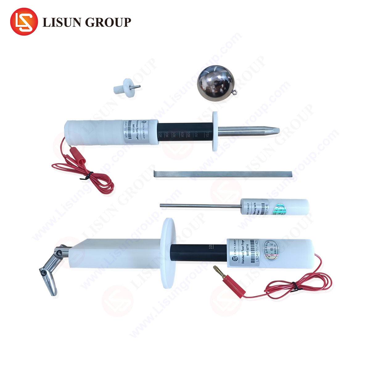
The physical construction of a compliant 0.5mm test probe is dictated by specifications that leave no room for interpretation. The primary element is a rigid, straight steel wire with a nominal diameter of 0.5mm (+0.01mm/-0.0mm is typical for precision instruments). This wire is terminated with a hemispherical tip, the radius of which is precisely defined—often 0.25mm—to prevent sharp edges that could damage equipment or provide unrealistic penetration. The wire’s length is sufficient to apply the necessary force and reach potential hazards, commonly 100mm or as specified by the relevant standard (e.g., IEC 61032, IEC 60529).
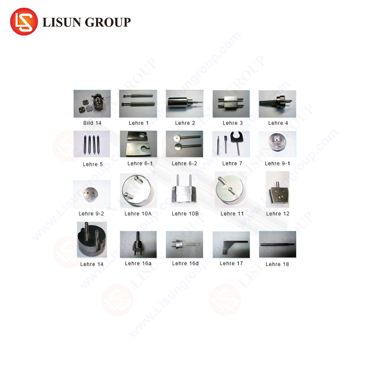
The LISUN Test Finger, Test Probe, Test Pin system exemplifies this precision engineering. Constructed from hardened stainless steel, the probe offers exceptional resistance to bending or deformation during repeated application, ensuring consistent test results over its operational lifespan. The handle is ergonomically designed to allow the technician to apply the specified force without slippage or angular deviation. Crucially, the system often includes interchangeable tips or a complete set of probes to comply with various standards (like the 1.0mm probe for different IP codes or the articulated test finger for IEC 61032), but the 0.5mm variant remains the most stringent for live part accessibility. Calibration certificates traceable to national standards are a non-negotiable accompaniment, verifying the dimensional accuracy of the wire diameter and tip geometry.
Governing Standards and Testing Protocols: IEC 61032 and Beyond
The deployment of the 0.5mm probe is not arbitrary but is strictly codified within international safety standards. The paramount standard is IEC 61032:1997, “Protection of persons and equipment by enclosures – Probes for verification.” This document provides the definitive specifications for the probe’s dimensions, material, and rigidity. It also outlines the test procedure: the probe is to be inserted into any opening in the enclosure with a force not exceeding 1 Newton (N). No articulated or jointed movement is applied to the 0.5mm probe; it is a straight, rigid intrusion test.
Furthermore, this probe is referenced within a multitude of derivative product family standards. For instance, IEC 60529 (Degrees of Protection provided by Enclosures – IP Code) references probe 13 from IEC 61032 for testing against access to hazardous parts (IP Code digit 2). Standards for Information Technology Equipment (IEC 60950-1, now superseded by IEC 62368-1), Household and Similar Electrical Appliances (IEC 60335-1), and Lighting (IEC 60598-1) all incorporate the use of the 0.5mm probe to verify compliance with clauses related to protection against access to live parts. The test’s outcome is absolute: if the probe contacts a live part at a voltage greater than the safety extra-low voltage (SELV) limit, or enters a compartment containing such a part, the construction is deemed non-compliant.
Operational Mechanics and Failure Mode Analysis
The testing principle is mechanically straightforward but requires meticulous execution. The technician identifies all openings, vents, grilles, seams, and gaps in the equipment’s external enclosure. This includes areas around controls, connectors, and between mating parts. The 0.5mm probe is then deliberately inserted into each opening. The 1N force limit is critical; excessive force can distort plastic enclosures or defeat interlocks, creating a false failure. The probe is manipulated to seek any possible path, but without bending or hooking.
A successful test results in the probe being stopped by internal barriers, such as baffles, secondary inner enclosures, or distance through air and creepage. A failure occurs upon contact with a conductive part that could be hazardous. It is important to note that contact with an unearthed conductive part (e.g., an ungrounded heatsink or transformer core) may also constitute a failure, as a fault condition could render it live. The LISUN probe’s rigidity ensures that if a path exists, it will be found, eliminating false negatives caused by a flexible probe deflecting. Post-test, the equipment is often subjected to a dielectric strength test (hipot test) to ensure the probe did not damage internal insulation during the procedure.
Cross-Industry Application Scenarios and Risk Mitigation
The universality of the access probe test stems from the commonality of shock risk. Its application spans numerous industries, each with unique form factors and user interaction models.
- Electrical and Electronic Equipment & Industrial Control Systems: Here, probes verify that ventilation slots in PLC cabinets, drive enclosures, or power supply cases do not allow tools or wires to contact busbars, terminal blocks, or PCB-mounted components.
- Household Appliances and Consumer Electronics: Openings for airflow in televisions, audio amplifiers, kitchen appliances, and power tool housings are tested. A common failure point is the gap between a plastic outer shell and an internal metal chassis.
- Automotive Electronics: Under-dash control units, sensor housings, and infotainment systems are tested to ensure that in the confined, vibration-prone, and potentially metallic environment of a vehicle, no accessible openings exist.
- Lighting Fixtures: Recessed lighting housings, streetlight control gear compartments, and the seams in LED panel lights are scrutinized to prevent contact with the mains input connections or driver output.
- Telecommunications Equipment: Data switches, router vents, and base station modules are tested, as they are often installed in accessible office or industrial environments.
- Medical Devices: For devices not requiring a sterile field, such as external power supplies for patient monitors or control units for therapeutic equipment, probe testing is vital to protect both clinicians and patients from incidental contact.
- Aerospace and Aviation Components: While meeting additional environmental standards, in-flight entertainment systems, galley power units, and control panel enclosures must still pass fundamental accessibility checks.
- Electrical Components: Sockets, switches, and connector housings are tested at their mating seams and mounting holes to ensure live terminals are fully recessed.
- Cable and Wiring Systems: Access points to wiring in ducts or connection chambers are evaluated.
- Office Equipment & Toy and Children’s Products: Printers, photocopiers, and battery-operated toys with service openings are tested to protect curious users from internal circuits, particularly those containing capacitors that may retain charge.
Comparative Advantages of Calibrated Test Probe Systems
Utilizing a generic, uncalibrated piece of wire for this test introduces significant liability and risk. A calibrated system like the LISUN Test Finger, Test Probe, Test Pin provides several definitive advantages. First is Metrological Traceability: The calibration certificate provides legal and technical assurance that the probe dimensions are within the tolerances required by the standard, making test results defensible during third-party certification audits. Second is Durability and Consistency: High-quality stainless steel resists corrosion and maintains its straightness, whereas a substitute may bend, kink, or wear, altering its effective diameter and compromising test integrity. Third is Ergonomics and Repeatability: A properly designed handle allows for accurate application of the 1N force, improving inter-technician repeatability. Finally, Comprehensive Compliance: Offering a full kit that includes not just the 0.5mm probe but also other standardized probes (articulated finger, 1.0mm wire, etc.) ensures a laboratory or manufacturer can address all relevant standards with one validated toolset, streamlining the compliance workflow.
Integration into a Broader Product Safety Verification Regime
It is imperative to contextualize the 0.5mm probe test as one element within a holistic safety engineering strategy. It primarily addresses the hazard of direct contact. It works in concert with other tests evaluating indirect contact (protection by earthing), insulation (dielectric strength, creepage, and clearance), and thermal and fire risks. For example, a probe may not contact a live part, but if it passes through an opening and reduces clearance below the required minimum, the product may still fail subsequent electric strength or impulse voltage tests. Therefore, the probe test is typically conducted early in the safety evaluation sequence, as a failure here often indicates a fundamental design flaw that must be rectified before more complex testing proceeds.
FAQ Section
Q1: Can a 0.5mm diameter sewing needle or paperclip be used as a substitute for a calibrated test probe?
A1: No. Substitutes lack the precise dimensional tolerances, specified tip geometry, and material rigidity mandated by IEC 61032. They may bend, have irregular tips, or be of incorrect diameter, leading to both false passes and false failures. Regulatory bodies and test laboratories require calibrated equipment for valid certification.
Q2: If my product has passed the 0.5mm probe test, does it automatically achieve a specific IP (Ingress Protection) rating?
A2: Not necessarily. Passing the 0.5mm probe test is a requirement for IP2X (protection against solid objects greater than 12.5mm) and is part of the test for higher second-digit ratings concerning hazardous part access. However, a full IP rating also requires testing for water ingress (first digit) and often additional probe tests (e.g., 1.0mm wire for IP4X). The probe test is one component of the IP rating system.
Q3: How often should a test probe like the LISUN system be recalibrated?
A3: Recalibration intervals depend on usage frequency, handling, and the quality management system of the testing entity. Typical intervals range from 12 to 24 months. Regular visual inspection for damage, bends, or tip deformation should be conducted before each use, and the probe should be withdrawn from service immediately if any defect is suspected.
Q4: Are there any openings that are explicitly exempt from this test?
A4: Yes, standards typically exempt openings that are only accessible when the equipment is in a service mode, provided that such service access is clearly indicated and requires a tool to activate. Openings that remain accessible during normal user operation, even if a tool is theoretically needed to create them, are generally not exempt.
Q5: What is the consequence of the probe contacting a grounded (earthed) metal part inside the enclosure?
A5: Contact with a reliably earthed part is usually permissible, as a fault condition would not make it hazardous. However, the earthing must be evaluated separately for continuity and robustness. Contact with an unearthed conductive part, even if not intentionally live, is often considered a failure, as a single fault (e.g., insulation failure) could energize it. The specific product standard must always be consulted for the definitive interpretation.