


An Analytical Framework for Pluggable Connection Safety: The Role of DIN VDE 0620-1 Gauge 3
The global marketplace for plugs, socket-outlets, and associated interconnection devices is characterized by a complex tapestry of regional standards and technical requirements. Ensuring the safety, interoperability, and mechanical integrity of these ubiquitous components is a paramount concern for manufacturers, testing laboratories, and certification bodies worldwide. Central to this endeavor is the German standard DIN VDE 0620-1, which specifies safety requirements for plugs and socket-outlets for domestic and similar purposes. Within the framework of this standard, a specific tool, the gauge for checking the protection against electric shock, emerges as a critical instrument for quantitative verification. This article provides a detailed examination of the DIN VDE 0620-1 Gauge 3, its functional principles, and its indispensable role in the modern quality assurance process, with a specific focus on the implementation of these testing protocols by advanced instrumentation such as the LISUN Gauges for Plugs and Sockets.
Fundamental Principles of Mechanical Safety in Plug and Socket Design
The primary safety objectives for any plug and socket-outlet system are the prevention of electric shock and the mitigation of fire risk. These objectives are intrinsically linked to the mechanical design and dimensional tolerances of the components. A socket-outlet must be designed to prevent access to live parts, not only during normal operation but also under conditions of partial insertion or misalignment of a plug. The standard test finger, a universal tool for assessing accessibility to hazardous parts, is often insufficient for evaluating the nuanced risks presented by the apertures of a socket-outlet. This is where specialized gauges, defined with precise geometries, become necessary. They simulate worst-case scenarios of plug insertion and probe the socket’s protective shutters or contact apertures to verify that a standardized test probe cannot make contact with live parts. The DIN VDE 0620-1 standard meticulously defines several such gauges, with Gauge 3 being specifically engineered for this critical assessment of shock protection.
Deconstructing the DIN VDE 0620-1 Gauge 3: Geometry and Application
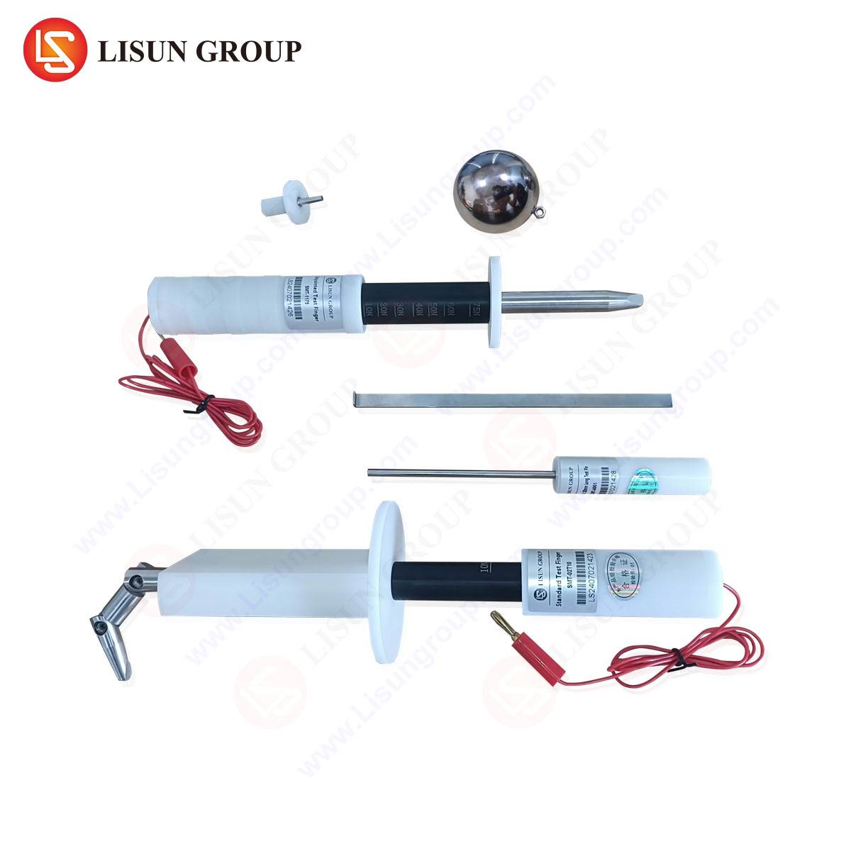
DIN VDE 0620-1 Gauge 3 is not a singular tool but a set of two distinct, yet functionally related, gauges designated as Gauge 3A and Gauge 3B. Their design is predicated on simulating a scenario where a plug is incorrectly inserted or only partially engaged with the socket-outlet, thereby potentially exposing live contacts.
Gauge 3A is designed to test the protection afforded by the socket-outlet when a plug is inserted into only one of the contact apertures. Its geometry is a precise representation of the plug pin, but with a crucial modification: it includes a lateral extension or “wing” that applies a force to the protective shutter mechanism of the adjacent, unused contact aperture. The test procedure involves inserting Gauge 3A into one aperture with a specified force, typically 1 Newton, and simultaneously attempting to insert a standard test pin into the adjacent aperture. The socket-outlet is deemed compliant only if the shutter mechanism remains effectively closed, preventing the test pin from contacting the live parts behind the second aperture.
Gauge 3B, conversely, is a more complex probe intended to verify that a person cannot access live parts through the socket-outlet’s apertures using a foreign object. It is a jointed, articulated finger-like probe that can be manipulated to simulate the insertion of a small tool or wire. The application of Gauge 3B involves inserting the probe into any aperture without operating the shutter mechanism and attempting to make contact with live parts from various angles. The stringent requirement is that the probe must not establish electrical contact with parts that are live during normal operation.
The material composition and dimensional accuracy of these gauges are critical. They are typically manufactured from high-strength, dimensionally stable insulating materials to prevent any electrical conductivity during testing. The tolerances for every dimension—length, diameter, angle, and radius—are explicitly defined in the standard, often to within hundredths of a millimeter. This precision ensures that test results are reproducible and consistent across different laboratories and manufacturing sites, forming a universal benchmark for safety.
Integration of Standardized Gauging in Automated Test Systems
While manual application of these gauges by a trained technician is a valid testing method, the modern high-volume manufacturing environment demands higher efficiency, repeatability, and data integrity. This has led to the development of automated test systems that integrate the functional principles of DIN VDE 0620-1 Gauge 3 into their operational protocols. The LISUN LPSC-2000 Series Plug and Socket Gauge System exemplifies this technological evolution.
This system incorporates servo-driven, precision-machined probes that replicate the geometry and application forces of the standard gauges. The testing sequence is fully automated and programmable. For a given socket-outlet type, the system will sequentially deploy probes equivalent to Gauge 3A and Gauge 3B, applying the exact forces and movements stipulated by the standard. Integrated sensors, including contact detection circuits and force transducers, objectively determine pass/fail status. This automation eliminates human error and subjective judgment, providing quantifiable and auditable data for every unit tested. The system’s software can be configured for various international standards beyond DIN VDE 0620-1, making it a versatile platform for manufacturers serving global markets.
Table 1: Key Specifications of an Automated Gauge Test System (e.g., LISUN LPSC-2000)
| Parameter | Specification | Relevance to DIN VDE 0620-1 |
|---|---|---|
| Probe Actuation | Servo motor with precision ball screw | Ensures smooth, accurate application and repeatable force for Gauge 3A/B simulation. |
| Applied Force Range | 0.1 N to 10 N, programmable | Covers the 1 N force requirement for Gauge 3A and allows for calibration to other standards. |
| Contact Detection | High-sensitivity electrical circuit (e.g., 40V AC, 0.1mA max) | Objectively determines if the probe has made electrical contact with a live part, a core function of Gauge 3B. |
| Positioning Accuracy | ±0.1 mm | Critical for accurately aligning the probe with the socket apertures, ensuring test validity. |
| Data Logging | Test results, force curves, timestamps | Provides traceable records for quality audits and production batch analysis. |
Industrial Application and Compliance Verification Workflows
The deployment of DIN VDE 0620-1 Gauge 3 testing, whether manual or automated, is integrated into a broader product development and quality control lifecycle. During the Research and Development phase, engineers use these gauges to validate prototype designs long before mass production. Iterative testing allows for the refinement of shutter mechanisms and internal barriers to ensure inherent compliance.
In the Production environment, sampling plans are typically established whereby a statistically significant number of units from a production batch are subjected to gauge testing. Automated systems like the LISUN LPSC-2000 are particularly advantageous here, as they can be integrated into end-of-line test stations, performing the check in a matter of seconds without slowing down the production flow. This provides real-time feedback on the manufacturing process; a sudden increase in gauge test failures may indicate tooling wear or a fault in the injection molding process for the socket’s housing.
For Third-Party Certification bodies, such as VDE, TÜV, or other National Certification Bodies, the use of certified reference gauges is mandatory for type-testing and surveillance audits. The gauges used by these organizations are themselves calibrated against national standards, creating a chain of traceability that underpins the entire safety certification ecosystem. The objective data produced by automated systems provides compelling evidence of consistent compliance during these audits.
Comparative Advantages of Automated Gauge Testing Systems
The transition from manual gauge testing to automated systems offers several distinct technical and operational advantages that extend beyond simple labor savings.
Enhanced Repeatability and Reproducibility (R&R): Human operators may apply force at slightly different angles or with inconsistent pressure. An automated system applies the exact same force vector and sequence every time, dramatically improving the R&R of the test, a key metric in any quality management system like ISO 9001.
Objective and Unambiguous Results: The determination of a “fail” in a manual Gauge 3B test can be subjective—did the probe feel like it touched a live part? Automated systems remove this ambiguity. The contact detection circuit provides a binary, data-driven result, eliminating potential disputes between manufacturers and certifiers.
Increased Throughput and Labor Optimization: Automated testing is significantly faster than manual inspection and does not require a highly skilled technician to perform the repetitive task. This frees qualified personnel for more complex analysis and problem-solving duties.
Comprehensive Data for Process Control: The data logging capabilities of systems like the LISUN LPSC-2000 allow for trend analysis. By tracking metrics such as the precise force required to open a shutter over time, manufacturers can perform predictive maintenance on molds and identify process drift before it leads to non-conforming products.
Frequently Asked Questions (FAQ)
Q1: Can a single automated test system be configured for different plug and socket standards, such as those from IEC, BS, or NF, in addition to DIN VDE?
Yes, advanced systems are designed with this flexibility in mind. They feature a library of interchangeable, precision-machined probes that replicate the specific gauges from various standards (e.g., IEC 60884-1, BS 1363). The system’s software allows the operator to select the relevant test program, which automatically configures the probe selection, applied forces, and test sequence.
Q2: How is the electrical contact detection circuit calibrated to ensure it does not damage the socket-outlet during testing?
The contact detection circuit is designed with safety as a primary consideration. It operates at a very low current and voltage, typically in the range of 0.1 mA at 40V AC. This energy level is sufficient to detect a reliable electrical path but is far below the threshold that could cause damage to the socket’s contacts or pose any safety risk to the operator or the equipment under test.
Q3: What is the typical calibration interval for the mechanical probes and force application mechanism in an automated gauge test system?
Calibration intervals are typically annual, aligning with most quality laboratory practices. However, the interval can be adjusted based on usage frequency and the manufacturer’s internal quality procedures. Calibration involves verifying the dimensional accuracy of the probes against a certified master set and validating the force application system’s accuracy using a traceable force meter.
Q4: If a socket-outlet fails the Gauge 3 test, what are the most common design or manufacturing flaws responsible?
A failure typically indicates an issue with the protective shutter mechanism. Common root causes include: insufficient spring force on the shutter, allowing it to be pushed open too easily; excessive tolerances between the shutter and its housing, creating a gap that the probe can exploit; or misalignment of the shutter assembly during the manufacturing or assembly process.
Q5: Is automated gauge testing a mandatory requirement for certification, or is manual testing still acceptable?
The standard defines the test method and the gauges, not the method of application. Therefore, both manual and automated testing are acceptable, provided they correctly implement the standard’s requirements. However, certification bodies are increasingly receptive to data from automated systems due to their superior objectivity, repeatability, and detailed audit trails, which can streamline the certification process.