


Dust Chamber Testing for Product Reliability: A Critical Analysis of Methodologies and Standards
The ingress of particulate matter represents a pervasive and often underestimated threat to the operational integrity and longevity of manufactured goods across a vast spectrum of industries. From the desiccated, silica-laden winds encountered by automotive electronics to the fibrous and conductive debris present in industrial control environments, dust and sand can induce catastrophic failures through abrasion, insulation breakdown, thermal impedance, and mechanical seizure. Consequently, dust chamber testing has evolved from a niche validation activity into a fundamental pillar of product reliability engineering. This article provides a technical examination of dust ingress testing, its governing standards, implementation methodologies, and the critical role of specialized equipment, with a focused analysis on the LISUN SC-015 Dust Sand Test Chamber as a representative advanced solution.
The Mechanisms of Particulate-Induced Failure in Engineered Systems
Particulate contamination does not constitute a singular failure mode but rather a synergistic catalyst for multiple degradation pathways. The primary mechanisms are categorized as abrasive wear, electrical malfunction, thermal management disruption, and mechanical interference. Abrasive wear occurs when hard particulates, such as quartz sand or industrial grit, impinge upon or are drawn across moving parts or protective coatings. This leads to the gradual erosion of seals, bearings, and optical surfaces, ultimately compromising functional tolerances and barrier integrity. In electrical and electronic equipment, including telecommunications gear and automotive sensor arrays, dust accumulation on printed circuit boards (PCBs) can create leakage paths, leading to short circuits or signal corruption, particularly in high-impedance circuits. Conductive particles, such as certain metal shavings or carbonaceous dust, pose an acute risk of bridging isolated conductors.
Furthermore, dust layers act as a thermal insulator, inhibiting the dissipation of heat from components like power semiconductors in industrial control systems or LED drivers in lighting fixtures. This can cause operational temperatures to exceed design limits, accelerating electromigration and reducing mean time between failures (MTBF). Mechanical interference is prevalent in devices with actuators or connectors, such as switches, sockets, and office equipment like printers, where particulate ingress can impede movement, block orifices, and prevent proper mating of interfaces. For aerospace and aviation components, where reliability is non-negotiable, testing against fine dust and sand is essential to ensure functionality in desert operations or during runway-induced debris clouds.
Governing Standards and Testing Protocols: IEC 60529 and Beyond
The international benchmark for dust ingress testing is delineated in IEC 60529, which classifies degrees of protection provided by enclosures via the IP (Ingress Protection) code. The code’s second numeral specifically addresses solid foreign objects. Of particular relevance are IP5X and IP6X ratings. IP5X, or “dust protected,” indicates that while dust may enter the enclosure, it cannot do so in sufficient quantity to interfere with satisfactory operation of the equipment. IP6X, “dust tight,” signifies no ingress of dust under defined test conditions. The test methodology prescribed involves placing the device under test (DUT) within a sealed chamber where fine talcum powder is circulated by a vacuum pump to create a consistent, low-pressure dust cloud. The test duration is typically 2, 4, or 8 hours, contingent upon the specific product standard.
Beyond IEC 60529, industry-specific standards impose more rigorous or tailored conditions. For instance, automotive electronics may be evaluated against ISO 20653 (derived from IEC 60529 but with automotive-specific severities) or SAE J575, which can include tests for sand abrasion. Military and aerospace specifications, such as MIL-STD-810G Method 510.5, prescribe severe blowing sand and dust tests with larger particle sizes and higher velocities to simulate operational environments for ground vehicles and aircraft. Medical devices, governed by standards like IEC 60601-1, must demonstrate that dust ingress will not compromise patient safety or essential performance, often requiring tests under both operational and storage conditions. The selection of the appropriate standard is therefore a critical first step in designing a valid reliability test regimen.
Architectural Principles of Modern Dust Test Chambers
A contemporary dust test chamber is an engineered system designed to generate, maintain, and control a homogeneous distribution of test dust within a defined volume. The core subsystems include the test chamber proper, a dust injection and circulation mechanism, a means of generating negative pressure differential, and integrated dust recovery and filtration. The chamber construction must be robust, typically using stainless steel or powder-coated mild steel, with a sealed viewing window and internal lighting for observation. The interior should be designed with smooth, rounded corners to facilitate dust circulation and cleaning.
The dust circulation system is paramount. Earlier designs often relied on simple agitation, but modern chambers like the LISUN SC-015 employ a closed-loop pneumatic system. A controlled volume of test dust (commonly Arizona Road Dust per ISO 12103-1, A2 Fine Test Dust, or talcum powder as specified) is stored in a reservoir. A compressed air or vacuum pump system fluidizes and injects the dust into the main chamber through strategically placed nozzles, creating a turbulent, suspended cloud. Simultaneously, a separate vacuum line connected to the DUT’s interior, or to the chamber if testing for overall enclosure integrity, creates the stipulated pressure differential (e.g., 2 kPa below atmospheric for IP5X/IP6X). This differential ensures dust is driven toward potential ingress points. Advanced chambers incorporate sensors to monitor and log internal temperature, humidity, and pressure differential in real-time, ensuring test parameter consistency.
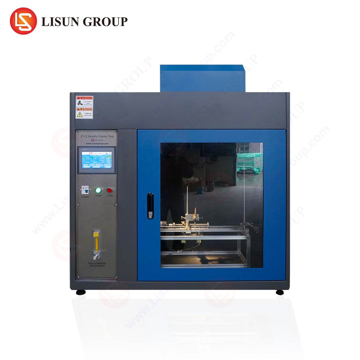
The LISUN SC-015 Dust Sand Test Chamber: Specifications and Operational Analysis
The LISUN SC-015 exemplifies the integration of these principles into a standardized testing instrument designed for rigorous compliance validation. Its design prioritizes repeatability, user safety, and adherence to international standards including IEC 60529, GB/T 4208, and ISO 20653.
Key Technical Specifications:
- Chamber Volume: 1 m³ (1000 liters), providing ample space for testing large or multiple DUTs such as household appliance control panels, industrial PLC cabinets, or automotive infotainment units.
- Dust Concentration: Adjustable and maintainable within a range of 2 kg/m³ to 4 kg/m³, allowing for tests of varying severity.
- Test Dust: Utilizes standardized dusts including talcum powder (mesh 200) for IP5X/IP6X tests and Arizona Road Dust (ISO 12103-1 A2) for sand and dust tests per automotive/military standards.
- Airflow System: Features a closed-loop circulation with a vortex blower, ensuring uniform dust distribution. The dust injection rate and circulation velocity are precisely controllable.
- Pressure Differential: Integrated vacuum pump system capable of maintaining a stable negative pressure up to 5 kPa below ambient, fully covering the requirements for IP testing and allowing for more severe user-defined tests.
- Control System: Microprocessor-based touchscreen controller with programmable logic for setting test duration, dust circulation cycles (intermittent or continuous), pressure differential, and temperature. Data logging functionality is standard.
- Safety & Filtration: Includes a high-efficiency primary filter and a HEPA final filter on the exhaust to protect laboratory environments and operators. An automatic shut-off and dust settling cycle is initiated at test conclusion to minimize exposure during sample retrieval.
Testing Principle and Workflow: The operational protocol for the SC-015 follows a deterministic sequence. The DUT is placed inside the chamber, and its internal cavity is connected to the vacuum port if testing for ingress into an enclosure. The desired test parameters—duration, pressure, dust concentration, and cycle timing—are input via the controller. Upon initiation, the chamber seals, and the circulation system fluidizes and injects the dust reservoir, creating a dense, suspended cloud. The vacuum system simultaneously draws a controlled airflow from inside the DUT, simulating the pressure differentials caused by thermal cycling or altitude changes. Throughout the test, the system maintains the specified environmental conditions. Post-test, the DUT is carefully inspected for dust penetration, often accompanied by functional testing to verify no degradation has occurred.
Industry-Specific Application Scenarios and Validation Objectives
The application of dust chamber testing is highly contextual, with validation objectives tailored to the product’s operational ecosystem.
- Electrical & Electronic Equipment / Industrial Control Systems: For variable frequency drives (VFDs) or programmable logic controllers (PLCs) installed in manufacturing plants, testing validates that cooling fan intakes are properly filtered and that board-level components are protected from conductive dust, preventing ground faults and signal noise.
- Automotive Electronics: Components like electronic control units (ECUs), radar sensors, and lighting fixtures are tested to IP6K9K (ISO 20653), which includes high-pressure, high-temperature water jets followed by dust exposure. This ensures reliability when mounted on vehicle underbodies or in wheel wells.
- Lighting Fixtures (Outdoor/Industrial): LED luminaires for street lighting or warehouse use must prevent dust accumulation on the thermal management fins and optical lenses. Ingress can reduce light output and cause overheating. Testing to IP65 or IP66 is common.
- Telecommunications Equipment: Outdoor 5G radios and base station hardware are subjected to prolonged dust tests to ensure passive cooling vents do not become clogged in arid or construction-adjacent environments, which would lead to thermal throttling and service interruption.
- Medical Devices: Portable diagnostic equipment or monitors used in field hospitals or ambulances must remain operational in dusty conditions. Testing here focuses on ensuring no particulate enters to interfere with delicate sensors, actuators, or internal airflow paths critical for cooling.
- Aerospace and Aviation Components: Avionics cooling systems and external sensors are tested against fine dust to simulate operation in desert airfields, ensuring no loss of function from particulate blocking critical orifices or heat exchangers.
- Cable and Wiring Systems: Connectors and gland seals are tested to verify their integrity, preventing dust from migrating along cable conduits into sensitive equipment areas.
Comparative Advantages of Integrated Testing Systems
The utilization of a dedicated, integrated chamber system such as the LISUN SC-015 offers distinct advantages over ad-hoc or legacy testing setups. Primarily, it ensures test repeatability and reproducibility, which are cornerstones of meaningful reliability data. Manual dust application or poorly controlled environments introduce significant variables, rendering comparative data between product generations or manufacturing batches unreliable. An automated chamber provides precise control over all critical parameters—dust density, airflow, pressure, and time—documenting these for audit trails.
Secondly, it enhances operator safety and environmental control. Containing the test dust within a sealed, negatively pressured chamber with post-test HEPA filtration minimizes occupational exposure to respirable particulates and prevents contamination of the laboratory. Furthermore, the efficiency and programmability of such systems reduce labor intensity and testing cycle times. A single programmed cycle can run unattended, incorporating complex sequences of dust circulation and settling phases, thereby optimizing laboratory resource utilization.
Interpreting Test Results and Implementing Design Improvements
A dust test is not merely a pass/fail gate but a diagnostic tool. Post-test analysis involves a meticulous visual inspection, often using borescopes for internal examination, followed by full functional testing. The pattern and location of dust ingress provide invaluable feedback to design engineers. For instance, dust tracing around a specific gasket indicates a sealing surface flaw or insufficient compression. Uniform dust coating on a PCB may point to inadequate sealing of cable entry points or ventilation labyrinths.
Corrective actions are then iterative. They may involve specifying higher-grade seal materials, redesigning gasket geometries, adding protective membranes over vents, or implementing more robust cable gland systems. Subsequent validation tests confirm the efficacy of these changes. This closed-loop process, facilitated by reliable and consistent chamber testing, directly contributes to enhanced product robustness, reduced warranty claims, and strengthened market reputation for reliability.
Future Trajectories in Particulate Reliability Testing
The evolution of dust testing continues in parallel with technological advancement. Emerging trends include the integration of combined environmental testing, where dust exposure is conducted concurrently with temperature cycling or humidity stress, providing a more accelerated and realistic simulation of field conditions. There is also a growing emphasis on testing with novel particulate types, such as graphene flakes or carbon nanotubes, which may be present in advanced manufacturing environments and pose unique electrical risks. Furthermore, the rise of sensor integration within test chambers allows for real-time monitoring of particulate density via laser scattering techniques, moving beyond prescribed durations to data-driven test endpoints based on actual exposure dosage.
Frequently Asked Questions (FAQ)
Q1: What is the critical difference between IP5X and IP6X testing in a chamber like the LISUN SC-015?
The fundamental difference lies in the acceptance criterion, not necessarily the test procedure. Both tests typically use similar talcum dust and a negative pressure differential. For IP5X, dust ingress is permitted provided it does not accumulate in a quantity or location that would impair safe operation or interfere with specified performance. For IP6X, the requirement is absolute: no dust ingress is allowed. The inspection post-test is therefore more stringent for IP6X, often involving internal examination under magnification and functional verification under rated load.
Q2: Can the SC-015 chamber accommodate tests for blowing sand, as required by some automotive or military standards?
Yes, the chamber’s design supports such tests. While the standard configuration is optimized for the fine talcum dust of IP tests, it can be loaded with Arizona Road Dust (ISO 12103-1 A2, or larger grades like A4). By adjusting the pneumatic injection system’s pressure and velocity, a more abrasive, sand-laden airflow can be simulated. However, for very high-velocity sand blasting tests specified in standards like MIL-STD-810, a dedicated sand and dust test apparatus with specialized nozzles and higher flow rates may be required.
Q3: How is the required negative pressure differential determined and maintained during a test?
The required differential is specified by the relevant test standard (e.g., 2 kPa for IEC 60529 IP5X/IP6X). The chamber’s vacuum pump system is calibrated to draw air from the interior of the Device Under Test (DUT) or from the chamber itself. A precision pressure sensor provides feedback to the controller, which modulates the vacuum pump to maintain a constant setpoint pressure throughout the test duration, compensating for any minor leaks or system variations.
Q4: What are the key maintenance considerations for ensuring the long-term accuracy of a dust test chamber?
Regular maintenance is crucial. Primary tasks include: the careful cleaning of the chamber interior after each test to prevent cross-contamination; inspection and replacement of seals on the door and viewing window to maintain integrity; checking and cleaning the dust circulation system’s nozzles and lines to prevent clogging; and periodic replacement of the HEPA and primary filters according to usage to ensure proper airflow and laboratory protection. Calibration of the pressure sensor and temperature probes should be performed annually.
Q5: For a product with multiple potential ingress points (e.g., vents, seams, connectors), how should it be oriented in the chamber?
The standard typically dictates that the test is conducted under the “most unfavorable” conditions. In practice, this often means testing the product in its normal operating orientation first. However, for a comprehensive validation, it is common practice to conduct sequential tests with the unit rotated to expose different faces to the dust cloud. Some standards may specify a rotating table within the chamber to ensure all surfaces are exposed during a single test cycle. The test plan should define the orientation(s) based on the product’s installation and usage profile.