


A Comprehensive Analysis of Dimensional Standardization and Verification in Electrical Appliances
Abstract
The dimensional conformity of electrical appliances, particularly the interface components of plugs and sockets, constitutes a foundational pillar of electrical safety, interoperability, and market access. This technical article examines the critical role of precise dimensional specification and verification within the global electrical manufacturing ecosystem. It delves into the interplay between international standards, manufacturing tolerances, and the specialized metrology required for compliance testing. A focused analysis of dedicated test equipment, such as the LISUN series of plug and socket gauges, illustrates the practical application of these principles in ensuring product integrity and regulatory adherence.
Introduction: The Imperative of Dimensional Precision in Electrical Interfaces
The physical dimensions of an electrical appliance extend beyond mere aesthetic or ergonomic considerations; they are intrinsically linked to functional performance and hazard prevention. Nowhere is this more critical than at the point of electrical connection—the plug and socket interface. An improperly dimensioned plug pin can result in inadequate contact pressure within a socket-outlet, leading to localized overheating, increased contact resistance, and potential ignition sources. Conversely, undersized socket apertures or incorrectly positioned earth pin locations can prevent engagement, encouraging unsafe user modifications. Dimensional non-compliance, therefore, represents a direct pathway to electrical failure, presenting risks of fire, electric shock, and equipment damage. Consequently, the development, manufacturing, and certification of plugs, socket-outlets, and appliance inlets rely upon a rigorous framework of dimensional standards and the precise gauging tools necessary to enforce them.
The Framework of International Dimensional Standards
Global and regional standards bodies, including the International Electrotechnical Commission (IEC), Underwriters Laboratories (UL), the European Committee for Electrotechnical Standardization (CENELEC), and others, publish exhaustive specifications governing the geometry of plugs and sockets. These documents, such as IEC 60083, IEC 60884-1, and AS/NZS 3112, do not merely suggest nominal measurements. They define permissible tolerance ranges for every critical dimension: pin diameter, length, and cross-section; pin spacing and orientation; the profile and dimensions of insulating sleeves; and the aperture sizes, positions, and depths within socket-outlets.
For example, the specification for a 10 A, 250 V plug according to a given standard may mandate a live pin diameter of 4.8 mm ±0.05 mm, with a center-to-center distance to the neutral pin of 18.6 mm ±0.2 mm. These tolerances balance manufacturability with safety, ensuring that any plug from a compliant manufacturer will mate securely and safely with any compliant socket-outlet, a principle known as interchangeability. The standards also define “go/no-go” gauging principles—the use of precision tools to verify that a component is within the allowed dimensional envelope, not simply close to a nominal value.
Manufacturing Tolerances and the Risk of Dimensional Drift
In high-volume production environments, tool wear, material flow variations in molding processes, and assembly inconsistencies can lead to dimensional drift. A pin mold may gradually wear, producing pins at the lower limit of the diameter tolerance. Simultaneously, the fixture holding pins for overmolding of the plug body may experience slight misalignment, affecting pin spacing. Individually, these variations may remain within specification, but their cumulative effect can push a product to the extreme edge of compliance or beyond. This drift is often insidious, not detectable by simple caliper measurement of a sample unit, but potentially catastrophic when a marginally undersized pin mates with a marginally undersized socket contact.
This underscores the necessity for statistical process control (SPC) in manufacturing, which relies on frequent, accurate measurement using gauges that reflect the actual mating conditions defined by standards. Dimensional verification thus transitions from a final quality audit checkpoint to an integrated component of the production process itself.
Principles of Dimensional Verification: Go/No-Go Gauging
The methodology for testing dimensional compliance is predominantly based on the go/no-go gauge system, a binary assessment tool derived directly from the standard’s requirements. A “go” gauge represents the maximum material condition (e.g., the smallest permissible socket aperture or the largest permissible plug pin), while a “no-go” gauge represents the minimum material condition (e.g., the largest permissible socket aperture or the smallest permissible plug pin). A compliant product must accept the “go” gauge and reject the “no-go” gauge under specified forces.
This system is elegantly efficient for production-line testing. It does not provide a quantitative measurement (e.g., 4.78 mm) but a definitive qualitative verdict: compliant or non-compliant. The design and manufacture of these gauges are themselves held to exceptionally tight tolerances, typically an order of magnitude tighter than the product specification they are verifying, to ensure measurement integrity.
LISUN Gauges for Plugs and Sockets: A Technical Examination
LISUN produces a comprehensive suite of gauges designed specifically for the verification of plugs, socket-outlets, and appliance couplers to major international standards. These instruments embody the application of go/no-go principles with a high degree of specialization and repeatability.
-
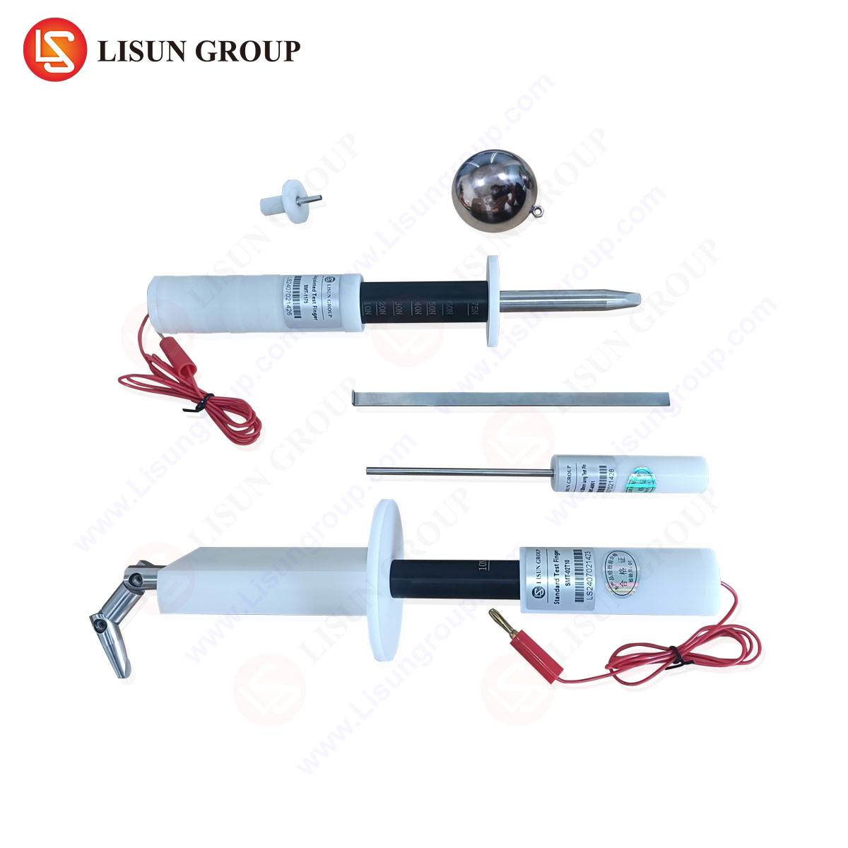
Product Specifications and Construction: LISUN gauges are precision-machined from hardened tool steel or other durable alloys to resist wear and maintain calibration over extended use. Their specifications are directly transcribed from the referenced standard. A typical set for a plug, for instance, may include:
- A Pin Gauge Set: Individual “go” and “no-go” ring gauges for verifying the diameter of live, neutral, and earth pins.
- A Pin Spacing Gauge: A plate with precisely spaced holes to check the center-to-center distances between pins. The “go” side accepts the plug pins when spacing is equal to or greater than the minimum; the “no-go” side must not accept the plug if spacing is equal to or less than the maximum.
- An Outline Gauge (Template Gauge): Verifies the overall profile and dimensions of the plug body, including the correct size and position of the insulating sleeves on the pins.
- A Socket-Outlet Gauge Set: Includes pin probes of specified diameters and lengths (“go” and “no-go”) to verify contact aperture sizes, depth of penetration, and shutter operation (where applicable).
-
Testing Principles in Practice: The use of these gauges follows a strict protocol. For a 13 A rectangular-pin plug to BS 1363, the tester would first use the outline gauge to ensure the plug body fits within the prescribed template. Next, the pin spacing gauge would be applied to confirm correct pin alignment. Finally, each pin’s diameter would be checked with the respective ring gauges. Each test applies a calibrated force—often via a dead weight or spring mechanism specified in the standard—to ensure the result is not subjective. A plug that fails any single gauge is deemed non-compliant.
-
Industry Use Cases and Applications: The primary application is within Quality Assurance laboratories of plug, socket, and appliance manufacturers, serving for incoming component inspection, in-process control, and final product certification. Third-party testing and certification bodies (e.g., TÜV, Intertek, UL) rely on such gauges as normative equipment for granting safety marks (CE, UKCA, ETL, etc.). National regulators and customs authorities may employ them for market surveillance, verifying that imported electrical goods adhere to national dimensional requirements, thus preventing substandard or counterfeit products from entering the supply chain.
-
Competitive Advantages of Specialized Gauge Systems: The value of a system like LISUN’s lies in its completeness, traceability, and standardization. Advantages include:
- Direct Standard Compliance: Each gauge set is manufactured to the exact dimensions and tolerances stipulated in a specific, published standard, removing interpretation error.
- Metrological Traceability: High-grade gauges are calibrated against reference masters, which are in turn traceable to national metrology institutes, ensuring global recognition of test results.
- Operational Efficiency: The go/no-go system allows for rapid testing by production line personnel without requiring advanced metrology skills, facilitating high-frequency sampling.
- Durability and Consistency: The use of hardened materials minimizes gauge wear, a critical factor in maintaining long-term measurement consistency, which is often a point of failure with softer gauge materials.
Integrating Dimensional Verification into a Holistic Compliance Strategy
It is crucial to position dimensional gauging within the broader context of type testing and routine testing. Dimensional checks are a subset of a comprehensive suite of tests that includes electrical, mechanical, thermal, and durability assessments. For example, a socket-outlet must not only accept the standard gauge pins but must also demonstrate adequate contact pressure (verified by a contact thermometer test), withstand mechanical stress (verified by a plug insertion/withdrawal cycle test), and provide sufficient insulation resistance and electric strength. Dimensional correctness is the prerequisite that enables these subsequent safety tests to be meaningful; an incorrectly sized product will not be tested under representative real-world conditions.
The Impact of Ergonomic and Industrial Design on Appliance Dimensions
While the connection interface is heavily standardized, the overall form factor of the appliance is influenced by ergonomic, functional, and market-driven design choices. The dimensions of a power tool handle, a kitchen appliance housing, or a consumer electronics enclosure are optimized for user grip, internal component layout, heat dissipation, and aesthetic appeal. However, these designs must always accommodate the standardized plug or appliance inlet, and the appliance’s weight and form must not exert undue mechanical stress on the plug/socket connection, a factor sometimes evaluated via a cord anchorage test that considers the appliance’s mass and typical use orientation.
Future Trends and Evolving Standards
The landscape of dimensional standardization is not static. Trends driving evolution include:
- Increased Safety Requirements: New editions of standards may introduce tighter tolerances or new gauge requirements to address observed failure modes.
- Global Harmonization: Efforts like the IECEE CB Scheme aim to reduce technical barriers to trade by promoting international acceptance of test results based on common standards, increasing the demand for globally recognized test equipment.
- New Technologies: The rise of electric vehicles has led to new standards for high-current AC and DC charging couplers (e.g., IEC 62196), requiring entirely new families of large, complex gauges to verify high-power connection interfaces.
- Smart Home Integration: The dimensions of standardized sockets may remain, but the incorporation of USB charging ports, shutters controlled by RFID or other mechanisms, and integrated energy monitoring will introduce new dimensional and functional parameters to be verified.
Conclusion
The precise dimensions of electrical appliances, mandated by international standards and verified through specialized gauging systems, form an invisible yet essential infrastructure for global electrical safety. The process from standard publication to gauge manufacture to production-line verification represents a critical chain of custody for product integrity. As electrical interfaces evolve in complexity and capability, the metrology supporting them—exemplified by dedicated tooling such as LISUN plug and socket gauges—will continue to be a indispensable element in the engineering, manufacturing, and certification lifecycle, ensuring that safety and interoperability remain inherent properties of the connected world.
FAQ Section
Q1: How often should plug and socket gauges be calibrated, and what is the process?
A1: Calibration frequency depends on usage intensity and quality system requirements (e.g., ISO 9001), but an annual cycle is common for active gauges. The process involves a accredited metrology laboratory measuring the gauge’s critical dimensions using equipment traceable to national standards. A calibration certificate reports the measured values and their uncertainty against the specified nominal dimensions and tolerances from the relevant standard. Gauges found to be outside their own specified tolerances must be taken out of service.
Q2: Can a single set of LISUN gauges be used to test products for multiple countries?
A2: No. Gauges are specific to a particular standard and the plug/socket type it defines. A gauge set for UK BS 1363 plugs is dimensionally different from a set for EU SCHUKO (CEE 7/7) plugs or Australian AS/NZS 3112 plugs. Manufacturers producing for multiple markets must possess a corresponding gauge set for each target standard. Some gauge systems are modular, allowing a common frame to be used with different insert plates for various standards.
Q3: What is the consequence of using worn or damaged gauges for compliance testing?
A3: Using compromised gauges invalidates the test results and poses a significant safety risk. A worn “no-go” gauge may accept an undersized component, allowing a non-compliant product to pass. A damaged “go” gauge may reject a compliant component, causing unnecessary production waste. Both scenarios undermine the integrity of the safety certification process and can lead to liability issues, product recalls, or market access revocation.
Q4: Beyond simple go/no-go checks, are there automated systems for dimensional verification in high-volume production?
A4: Yes. Automated optical inspection (AOI) systems using machine vision cameras can perform high-speed dimensional checks on pins and plug bodies. However, these systems require regular validation and calibration against physical master gauges (like those from LISUN) to ensure their programming and optical measurements remain accurate to the standard. Physical gauges remain the definitive reference and are often used for periodic system verification and audit purposes.
Q5: How are gauges used to test the safety shutters in modern socket-outlets?
A5: Specific shutter test probes are defined in standards like IEC 60884-1. These are part of the socket-outlet gauge set. They include a “child-safety” probe that simulates a single foreign object (e.g., a paperclip) and must not be able to make contact with live parts. Separate “go” pin probes, which simulate the simultaneous insertion of all plug pins, must open the shutters smoothly under a specified force. The gauges verify both that the shutters provide the required protection and that they do not offer excessive resistance to a correct plug.