


A Comprehensive Framework for the Validation and Verification of Electrical Connector Performance
The ubiquitous electrical connector, manifesting most commonly in the form of plugs and sockets, constitutes a critical juncture within any power distribution or electronic system. Its performance transcends mere conductivity; it is the primary guardian against electrical hazards, ensuring operational reliability, user safety, and long-term system integrity. Consequently, a rigorous, standardized testing regimen is not merely an engineering best practice but a fundamental requirement dictated by international safety standards and the imperative of risk mitigation. This article delineates the core principles, methodologies, and instrumentation essential for the comprehensive evaluation of electrical connectors, with particular emphasis on the validation of household and industrial plugs and sockets.
Fundamental Failure Modes and Corresponding Test Regimens
The degradation or failure of an electrical connector typically follows predictable physical and electrical pathways. A holistic testing strategy must therefore be designed to proactively simulate and measure susceptibility to these failure modes. The primary vectors include contact resistance instability, dielectric breakdown, thermal overload, mechanical wear, and environmental corrosion. Each vector demands a discrete yet complementary test protocol. For instance, elevated contact resistance, often a precursor to catastrophic failure, results from surface film formation, fretting corrosion, or insufficient contact force. Its measurement requires precise, low-resistance ohmmeters capable of discounting the influence of test lead resistance, often employing a four-wire Kelvin bridge methodology. Conversely, evaluating dielectric integrity involves subjecting the connector to high voltages—both AC and impulse—to ensure the insulation and creepage distances can withstand transient surges and operational overvoltages without breakdown.
Quantifying Mechanical Durability and Contact Integrity
The mechanical lifecycle of a plug and socket is defined by mating and unmating cycles, each imparting wear on contact surfaces, housings, and mechanical locking features. Standardized durability testing, such as that outlined in IEC 60884-1 for plugs and socket-outlets, mandates thousands of cycles under loaded conditions. The critical measurement during this process is the monitoring of electrical continuity throughout the cycle. A momentary discontinuity, even of millisecond duration, signifies contact bounce or wear-induced failure. This necessitates specialized equipment that can apply a standardized test current (often a low-voltage, low-current signal for detection purposes) and log any interruption. The apparatus must precisely control the mating/unmating speed and force to ensure repeatability, while sophisticated data acquisition systems capture transient events that would be invisible to standard multimeters.
Thermal Performance Assessment Under Operational Load
The thermal characteristics of a connector under load serve as a direct proxy for its electrical efficiency and safety. Poor contact design, inadequate conductor termination, or insufficient contact force will manifest as localized heating at the connector interface due to I²R losses. Temperature rise testing, therefore, is a non-negotiable validation step. The procedure involves subjecting the connector to its rated current in a controlled, draft-free environment until thermal equilibrium is achieved—a process that can take several hours. Temperature measurements are taken using calibrated thermocouples or infrared thermography at specified points on the pins, sleeves, and surrounding housing. Exceeding the maximum permissible temperature rise, as codified in standards like IEC 60512-5-2, indicates a design flaw that could lead to insulation degradation, contact softening, or fire risk. The test environment’s stability is paramount, as ambient fluctuations can corrupt results.
The Critical Role of Gauge Systems in Dimensional Compliance
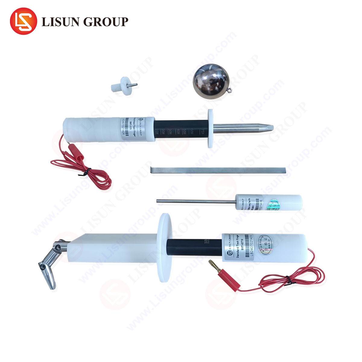
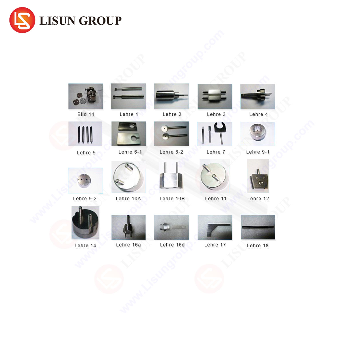
Perhaps the most fundamental, yet frequently underestimated, aspect of connector validation is dimensional conformance. The safety of a plug and socket system relies entirely on the precise geometry of pins, apertures, protective earth profiles, and shutter mechanisms. A plug pin even marginally undersized can lead to arcing and overheating; an oversized socket contact can cause dangerous insertion forces or permanent deformation. This is the domain of specialized gauge systems, which provide a pass/fail verification of critical dimensions as defined by national and international standards. These gauges are not general-purpose measuring tools like calipers; they are purpose-built, hardened steel artifacts that physically test the allowable geometric tolerances. Their application is binary: a designated “GO” gauge must fit under specified force, and a “NO-GO” gauge must not fit. This simple test validates safety-critical features such as pin diameter and length, the correct inter-pin spacing, the profile and depth of the earth pin for early-make/late-break safety, and the correct operation of socket shutters.
LISUN Gauges for Plugs and Sockets: Precision Instrumentation for Safety Validation
Within this essential category of dimensional testing, the LISUN series of gauges for plugs and sockets represents a calibrated reference standard for manufacturers and certification bodies. These gauge sets are engineered to the exacting dimensional specifications of relevant standards, including but not limited to IEC 60884-1, BS 1363, AS/NZS 3112, and NEMA configurations. A typical comprehensive set includes pin gauges (GO/NO-GO for line, neutral, and earth pins), spacing gauges, profile gauges for earth pins, and socket aperture test pins. Each gauge is manufactured from high-grade, wear-resistant tool steel, heat-treated for longevity, and meticulously ground to tolerances often within ±0.005mm to ensure authoritative test results.
The testing principle is one of physical simulation and interference checking. For example, the LISUN-1363-EARTH-PROFILE gauge will verify that the earth pin of a BS 1363 plug has the correct rectangular profile with the necessary chamfers, ensuring it will successfully engage the socket shutter mechanism before the line and neutral pins make contact. Similarly, the LISUN-60884-SOCKET-CHECK set includes a series of pin probes to verify that socket shutters open only when a valid earth pin is simulated, and remain closed against probes attempting to access the live contacts directly—a direct test of child safety provisions.
Industry Application in Manufacturing and Quality Assurance
The deployment of LISUN gauges spans the product lifecycle. In Research & Development, engineers use them to verify prototype tooling and first-article samples against target specifications. During mass production, they are a cornerstone of the quality assurance station, providing rapid, unambiguous checks for critical-to-safety dimensions on a statistical sampling basis. For third-party testing laboratories and certification agencies like UL, Intertek, or TÜV, these gauges are the definitive tools for type-test approval, ensuring a product submitted for certification conforms to the dimensional clauses of the standard before more complex electrical tests are even initiated. A failure at the gauge stage immediately indicates a non-conformance that must be addressed.
Advantages of Certified Gauge Systems Over Ad-hoc Measurement
The competitive advantage of utilizing a certified gauge system like LISUN’s lies in its objectivity, repeatability, and traceability. While a coordinate measuring machine (CMM) can measure a pin’s diameter to high precision, it cannot as effectively simulate the functional interaction of a plug entering a socket. Gauges provide a functional test. Furthermore, they eliminate operator interpretation, providing a clear pass/fail outcome that aligns perfectly with the requirements of the standard. Each gauge set is supplied with a certificate of calibration traceable to national metrology institutes, providing the documentary evidence required for ISO 9001 quality systems and regulatory audits. This metrological traceability transforms a simple physical check into a defensible quality metric.
Integrating Dimensional and Electrical Test Data for Holistic Analysis
Advanced connector validation does not treat dimensional and electrical tests as isolated silos. Correlative analysis is powerful. For instance, a connector that passes dimensional checks but exhibits a high temperature rise may suffer from suboptimal contact material or plating. Conversely, a plug that requires excessive insertion force (a metric often checked with a force gauge during gauge testing) may pass electrical tests initially but cause premature mechanical wear in the socket. Modern test laboratories therefore synthesize data from gauge checks, contact resistance measurements, temperature rise tests, and durability cycles to build a complete performance profile. This integrated approach allows for root-cause analysis far beyond what is possible with a single-metric test.
Standards Compliance as a Dynamic Framework
It is imperative to recognize that connector testing is not a static exercise. Standards such as IEC 60884, IEC 60320, and national derivatives are living documents, periodically revised to address new materials, technologies, and safety insights. Testing protocols and the associated equipment, including gauge dimensions, must evolve in lockstep. For example, recent amendments to socket standards have introduced more stringent tests for shutter resistance to static force and improved gauge designs to test them. A manufacturer’s commitment to ongoing compliance must therefore include a protocol for regularly reviewing and updating its test equipment, such as gauge sets, against the latest standard editions and amendments.
Conclusion
The assurance of electrical connector safety and reliability is a multifaceted engineering discipline founded on empirical validation. From the macro-scale thermal performance under load to the micro-scale precision of a pin’s profile, each test parameter interlinks to form a comprehensive safety net. Dimensional verification via certified gauge systems constitutes the foundational layer of this net, ensuring the basic geometry that enables safe mating and protects users. When integrated with a full suite of electrical, mechanical, and environmental tests, it provides a robust, defensible, and standards-compliant validation of product integrity, ultimately safeguarding both end-users and the manufacturers who serve them.
FAQ Section
Q1: How often should LISUN gauges be recalibrated in a production environment?
A: The recalibration interval depends on usage frequency and the requirements of your quality management system. For high-volume production checks, an annual recalibration is typical and often mandated by audit standards. Gauges used less frequently may be calibrated every two years. The provided calibration certificate will state a recommended interval, but the ultimate periodicity should be defined in the laboratory’s or factory’s controlled procedures, considering factors like wear and risk.
Q2: Can one set of LISUN gauges be used for testing connectors designed to different international standards?
A: No. Each major standard (e.g., BS 1363, AS/NZS 3112, IEC Type E/F) defines unique, non-interchangeable geometries for pins, sockets, and safety features. A gauge set is meticulously crafted for a specific standard and its national variants. Using a BS 1363 gauge to check an Australian AS/NZS 3112 plug would yield meaningless and non-compliant results. Manufacturers producing for multiple regions must possess a dedicated, calibrated gauge set for each applicable standard.
Q3: What is the functional difference between a “GO” gauge and a “NO-GO” gauge?
A: Their functions are complementary and definitive. A “GO” gauge represents the minimum acceptable material condition (e.g., the smallest allowable pin size). The part must fit this gauge with a specified, gentle force. A “NO-GO” gauge represents the maximum acceptable material condition (e.g., the largest allowable pin size). The part must not fit this gauge. A part that fits both has failed; a part that fits the “GO” but not the “NO-GO” has passed the dimensional test for that feature.
Q4: Beyond dimensional checks, what is the next critical test for a plug and socket assembly?
A: Following successful dimensional verification, the temperature rise test under rated current load is arguably the next most critical. It directly assesses the connector’s ability to carry its designated current safely without overheating. A failure here indicates fundamental issues with contact resistance, conductor sizing, or material properties that could lead to fire hazard, even if the plug and socket physically fit together correctly.
Q5: How are socket shutters functionally tested using gauge systems?
A: Specialized gauge sets include test pins that simulate various insertion scenarios. A “shutter opening” probe, which mimics the correct earth pin profile, must open the shutters with a defined force, allowing access to the live contact probes. Conversely, “shutter non-opening” probes, which may simulate a child inserting a foreign object like a rod or a pin without the correct earth profile, must be prevented from accessing the live contacts, typically withstanding a specified static force without opening. This two-part test validates the child-safety mechanism.