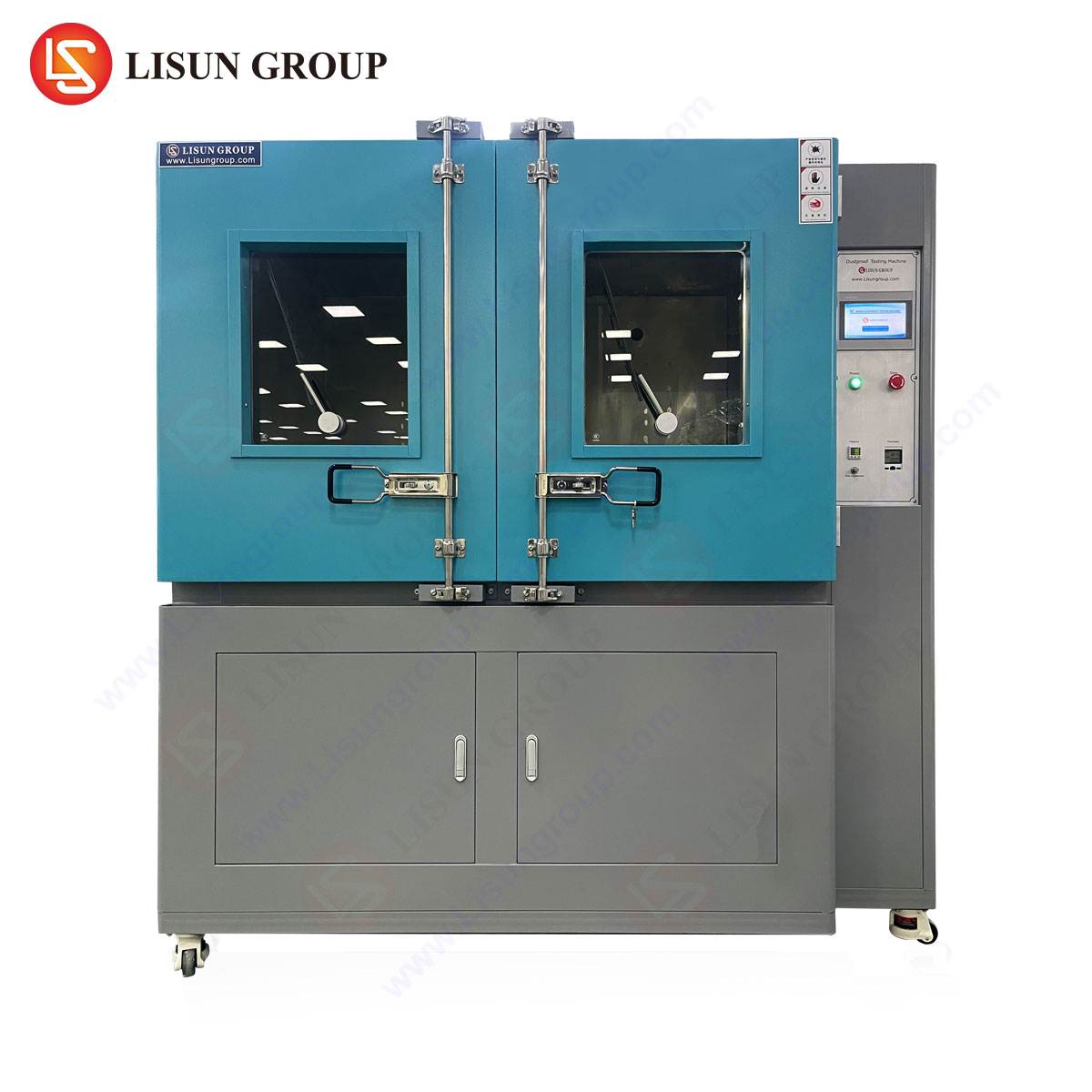


A Comprehensive Framework for Electrical Connector Testing: Adherence to VDE Standards and the Role of Specialized Instrumentation
Introduction: The Imperative of Standardized Connector Validation
The global ecosystem of electrical plugs and sockets constitutes a critical interface between power distribution networks and end-user equipment. The safety, reliability, and interoperability of these connectors are non-negotiable prerequisites, governed by a complex matrix of regional and international standards. Within the European sphere, and particularly in Germany, the VDE (Verband der Elektrotechnik, Elektronik und Informationstechnik) specifications represent a cornerstone of electrical safety engineering. VDE standards, such as those within the VDE 0620 series for plugs and socket-outlets, prescribe exhaustive testing protocols to verify mechanical integrity, electrical performance, and long-term durability under simulated operational and fault conditions. Compliance is not merely a regulatory formality but a fundamental engineering discipline that mitigates risks of electric shock, fire ignition, and mechanical failure. This article delineates the core testing methodologies mandated by relevant VDE standards and examines the specialized instrumentation, exemplified by the LISUN Gauges for Plugs and Sockets, essential for executing precise, repeatable, and standards-compliant validation.
Deconstructing VDE 0620: Mechanical and Dimensional Verification Protocols
The VDE 0620 standard family, particularly VDE 0620-1 for plugs and socket-outlets up to 250V, establishes stringent dimensional and mechanical requirements. These specifications ensure that connectors mate correctly, maintain secure contact pressure, and prevent access to live parts. Testing in this domain is predominantly geometrical and force-based.
Dimensional verification requires checking the plug pins and socket contact apertures against precisely defined tolerances. Parameters include pin diameter, length, cross-section, spacing (contact gap), and the profile of protective earth pins. Crucially, the standard also defines “go/no-go” gauges to check for safety-critical clearances and accessibility. For instance, a standardized test probe must not contact live parts in a socket-outlet when inserted in a prescribed manner. The mechanical strength of insulating bodies, the robustness of cord anchorage systems (strain relief), and the resistance of pins to bending are also assessed through static force tests. A plug must withstand a specified bending moment applied to its pins without permanent deformation exceeding defined limits, ensuring pins do not become misaligned or weakened in service.
Evaluating Electrical Performance and Safety Characteristics
Beyond physical dimensions, the electrical performance under both normal and abnormal conditions is rigorously examined. Key tests include:
- Contact Resistance and Temperature Rise: The connector must exhibit low electrical resistance at pin-to-socket interfaces to minimize power loss and heating under rated current. A temperature rise test, conducted by passing the rated current through the assembled connector until thermal equilibrium is reached, verifies that heating remains within safe limits (typically 52K for certain components as per VDE 0620-1). Excessive temperature rise can degrade insulation and pose a fire hazard.
- Dielectric Strength and Insulation Resistance: High-potential (hipot) testing applies an elevated AC or DC voltage between live parts and accessible conductive parts (e.g., between pins and the earth pin or external casing) for one minute. This verifies the integrity of the insulation, ensuring no breakdown or excessive leakage current occurs. Insulation resistance is measured with a DC voltage (e.g., 500V DC) to confirm the insulation material’s quality is sufficiently high, typically requiring values in the range of hundreds of megohms.
- Resistance to Heat, Fire, and Tracking: Material tests assess the non-flammability of insulating components via glow-wire tests (e.g., IEC 60695-2-11) and needle-flame tests. Comparative tracking index (CTI) measurements evaluate the material’s resistance to forming conductive paths on its surface under electrical stress in the presence of contaminants.
Endurance and Robustness: Simulating a Connector’s Service Life
Connectors are subjected to accelerated lifecycle testing to predict long-term reliability. A primary test is the mechanical endurance (durability) cycle. This involves a specified number of insertion and withdrawal cycles (e.g., 10,000 cycles for a socket-outlet per VDE 0620-1) using a standardized, automated test apparatus. The connector must function flawlessly throughout and pass electrical tests (contact resistance, dielectric strength) upon completion. This simulates years of normal use, checking for wear of contacts, degradation of mechanical springs, and loosening of components.
Additional robustness tests include resistance to impact, static load (for socket faces), and tests for resistance to arcing (for switches integrated into sockets). Environmental stress tests, such as damp heat cycling, may also be applied to assess performance under humid conditions.
The Critical Role of Specialized Gauging and Test Equipment
Accurate, traceable measurement is the foundation of compliance. General-purpose calipers and micrometers lack the specificity and required geometries for many VDE-mandated checks. This necessitates specialized gauging tools designed explicitly for the standard’s unique test fixtures and acceptance criteria. These tools are not merely measuring devices but are, in effect, physical embodiments of the standard’s requirements.
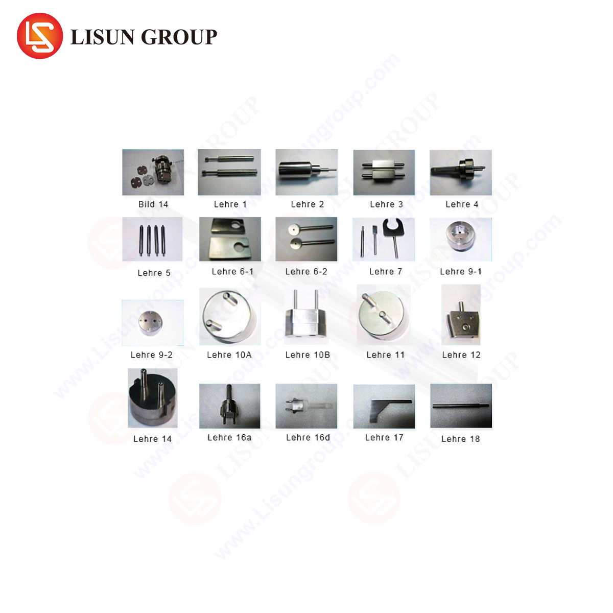
LISUN Gauges for Plugs and Sockets: A System for Conformity Assessment
The LISUN series of gauges for plugs and socket-outlets provides a calibrated, comprehensive toolkit for executing the dimensional and mechanical tests outlined in VDE 0620 and related international standards (e.g., BS, NF, etc.). These instruments are engineered to deliver the precision and repeatability demanded by certification bodies, quality assurance laboratories, and manufacturing facilities.
- Product Specifications and Testing Principles: The gauge sets typically comprise multiple individual gauges, each serving a distinct verification function. Common elements include:
- Pin Gauges: Precision cylindrical gauges for verifying the minimum and maximum diameters of line, neutral, and earth pins.
- Profile Gauges: Complex-form gauges to check the cross-sectional shape and dimensional limits of flat or rectangular pins (e.g., Schuko earth pins).
- Socket Gauge (Test Probe): A standardized finger-like probe with defined dimensions and applied force (e.g., 1N) to verify that live parts within a socket are not touchable. This directly tests compliance with protection against electric shock.
- Contact Gap Gauges: Feeler gauges of specified thicknesses to verify the minimum and maximum distances between socket contacts.
- Force Gauges & Bending Moment Apparatus: Specialized fixtures for applying calibrated forces to pins for bending tests or to socket-outlets for static load tests.
The testing principle is inherently binary for many checks: a “GO” gauge must fit under a specified force or condition, while a “NO-GO” gauge must not fit. This provides a clear, unambiguous pass/fail criterion for production line or laboratory use.
-
Industry Use Cases and Application: The primary application is within the quality control workflows of manufacturers producing plugs, sockets, travel adapters, and appliance inlets/couplers. They are indispensable during:
- First Article Inspection (FAI): Validating that new tooling or production samples conform to the standard before mass production.
- Incoming Quality Control (IQC): Verifying the conformity of purchased components, such as plug pins or socket contact assemblies.
- In-Process and Final Production Audits: Performing random sampling checks on the production line to ensure ongoing compliance and detect tooling wear or process drift.
- Certification Laboratory Support: Used by third-party testing laboratories (e.g., VDE, TÜV) as part of their type-testing and surveillance audit procedures.
-
Competitive Advantages in Technical Context: The value proposition of a system like the LISUN gauges lies in several technical and operational factors:
- Traceability and Certification: Each gauge set is supplied with a calibration certificate from an accredited laboratory, ensuring measurement traceability to national standards—a mandatory requirement for accredited testing.
- Material Durability: Manufactured from hardened tool steel or other wear-resistant materials, these gauges maintain their critical dimensions over thousands of uses, unlike 3D-printed or soft-metal improvised tools.
- Comprehensive Coverage: A complete set addresses all major dimensional checks in a single, organized kit, reducing the risk of oversight and improving testing efficiency.
- Ergonomic and Clear Design: Properly designed gauges incorporate handling features and are clearly marked with their function (GO/NO-GO, size), minimizing operator error and training time.
Integrating Gauging into a Holistic Test Regime
It is vital to position dimensional gauging within the complete test hierarchy. While gauges verify conformance to the drawn specification, they are a subset of the total validation required. A compliant product must successfully pass the full battery of electrical, thermal, mechanical endurance, and environmental tests. The gauges ensure the product enters this rigorous testing phase with a correct geometrical foundation. A connector that fails basic gauge checks will inevitably fail subsequent electrical safety tests, such as touch protection or dielectric strength.
Conclusion: Ensuring Safety Through Precision Measurement
The pathway to VDE compliance for electrical connectors is a multifaceted engineering challenge, blending precise mechanical tolerances with robust electrical and material science. Dimensional verification via specialized gauges is the essential first gate in this process, providing objective, repeatable evidence that a product’s design aligns with the safety intent of the standard. Instrumentation such as the LISUN Gauges for Plugs and Sockets operationalizes the often-abstract requirements of VDE 0620 into tangible, actionable production and quality control checks. In an industry where safety margins are quantified in millimeters and milliohms, the reliance on such calibrated, purpose-built tools is not merely best practice but a fundamental component of responsible manufacturing and credible product certification.
FAQ Section
Q1: Can a single set of LISUN Gauges be used for testing connectors designed to different national standards (e.g., German Schuko, French, British BS 1363)?
A: Typically, no. Each national standard (VDE, NF, BS) defines unique pin shapes, sizes, and socket configurations. A gauge set is specifically machined to the dimensional tolerances of a particular standard. Manufacturers producing for multiple markets require a dedicated gauge set for each standard family. Some comprehensive kits may include subsets for related types, but the gauges themselves are not universally interchangeable across differing specifications.
Q2: How frequently should these gauges be recalibrated in an industrial quality control setting?
A: Recalibration frequency depends on usage intensity, environmental conditions, and the quality system’s requirements (e.g., ISO 9001, IATF 16949). A common interval for active use in production is annually. However, if gauges are used very frequently or subjected to potential damage, a shorter interval (e.g., six months) may be warranted. The calibration certificate provides a recommended interval, but the user’s quality control plan should define the formal recalibration schedule based on a risk assessment.
Q3: What is the consequence of using a worn or uncalibrated gauge for production checks?
A: Using uncalibrated or worn gauges introduces significant risk. A worn “NO-GO” gauge might pass an undersized component, potentially leading to unsafe loose connections or accessible live parts. Conversely, a worn “GO” gauge might reject conforming parts, causing unnecessary production waste. More critically, it invalidates the quality data, meaning products shipped with a certificate of conformity may not actually meet the standard, exposing the manufacturer to liability, recall risks, and reputational damage.
Q4: Beyond dimensional checks, what is the most critical electrical test for a plug and socket assembly?
A: While all prescribed tests are safety-critical, the dielectric strength (hipot) test and the temperature rise test are particularly fundamental. The hipot test directly verifies the integrity of the primary insulation barrier against electric shock. The temperature rise test validates the connector’s ability to carry its rated current continuously without overheating, which is a primary cause of insulation degradation and potential fire initiation over the product’s lifetime.
Q5: In the context of the bending test on plug pins, how is the applied force or moment calibrated and verified?
A: The bending test apparatus specified in standards like VDE 0620-1 must apply a precise bending moment (Newton-meters) or force at a defined distance from the plug face. Calibration is performed using a certified torque wrench or a calibrated force gauge and lever arm system. The test equipment itself is periodically verified to ensure it applies the correct load as per the standard’s stipulation, ensuring the test’s severity is neither excessive nor insufficient.