


Comprehensive Methodologies for the Validation of Electrical Plug and Socket Safety and Performance
The global proliferation of electrical devices, coupled with increasingly stringent safety regulations, has elevated the importance of rigorous plug and socket testing from a manufacturing checkpoint to a critical component of product lifecycle validation. These interface points represent the primary juncture for electrical energy transfer to end-user equipment; their failure can precipitate consequences ranging from operational interruption to catastrophic safety hazards, including fire and electric shock. Consequently, a systematic, standards-based testing regimen is indispensable for manufacturers, certification bodies, and quality assurance laboratories. This article delineates the core testing principles, applicable international standards, and the instrumental role of specialized equipment, with a focused examination of the LISUN Gauges for Plugs and Sockets as a paradigm for precision metrology in this domain.
Fundamental Mechanical and Dimensional Verification Protocols
Prior to any electrical assessment, mechanical and dimensional conformity establishes the foundational integrity of a plug or socket. Incompatible dimensions are a primary source of poor contact, overheating, and user force application that can damage both the connector and the receptacle. Testing in this phase is predominantly comparative, utilizing precision-engineered gauges to verify critical parameters against the tolerances specified in standards such as IEC 60884-1, BS 1363, or AS/NZS 3112.
Key dimensional checks include pin configuration, pin size and spacing, socket contact geometry, and the dimensions of protective features like shutters. For example, the verification of a BS 1363 plug involves confirming the exact length, diameter, and separation of the line, neutral, and earth pins, as well as the profile of the insulated sleeve. Similarly, socket testing mandates checks on entry aperture sizes, shutter mechanism operation, and contact alignment. The use of “GO/NO-GO” gauges is prevalent here; a “GO” gauge must fit freely under its own weight into the specified dimension, while a “NO-GO” gauge must not enter under a defined minimal force. This binary pass/fail methodology provides unambiguous results for production line quality control.
Evaluating Electrical Contact Integrity and Circuit Continuity
Once dimensional compliance is assured, the electrical performance of the conductive path must be quantified. The primary metric is contact resistance, measured in milliohms (mΩ). Excessive resistance at the pin-socket interface generates localized Joule heating, degrading materials over time and potentially initiating thermal runaway. Testing is performed by inserting a plug, or a standardized test probe representing a plug, into the socket and passing a stabilized direct current (typically 10A to 25A as per standard requirements) through the contact. The voltage drop across the connection is measured using a four-wire (Kelvin) method to eliminate lead resistance, and Ohm’s Law is applied to calculate resistance.
Acceptable thresholds are strictly defined; for instance, many standards require the total resistance of the socket contacts, including the internal wiring, to not exceed a value like 15 mΩ. Beyond initial verification, endurance testing assesses contact integrity over simulated lifecycle use. Automated equipment repeatedly inserts and withdraws test probes—often thousands of cycles—while monitoring resistance intermittently. A significant increase in resistance over the test cycle indicates wear, poor contact spring design, or material degradation.
Thermal Stress Endurance and Overload Simulation
Plugs and sockets are subjected to thermal stress both from ambient environmental conditions and from internal heating due to current flow. Temperature rise testing evaluates the latter. A sample is placed in a controlled, draft-free test chamber and connected to a calibrated load. It is then energized at its rated current until thermal equilibrium is achieved, which can take several hours. Thermocouples attached to critical points—pin terminals, socket contacts, and external surfaces—record temperature increases. Standards such as IEC 60884-1 stipulate maximum permissible temperature rises (e.g., 52 Kelvin for certain components) above ambient to ensure insulation materials are not compromised and user-accessible surfaces remain safe to touch.
Overload testing simulates abnormal conditions, such as a faulty appliance drawing sustained high current. The device is subjected to a current significantly above its rating (e.g., 150% of rated current) for a prescribed period. Performance is deemed acceptable if no hazardous conditions arise, such as melting, ignition, or sustained arcing.
Mechanical Endurance: Simulating a Product’s Operational Lifespan
The mechanical durability of a socket, in particular, is paramount. Mechanical endurance test apparatus automates the process of plug insertion and withdrawal. A standardized test probe, with dimensions at the maximum allowable tolerance to simulate a “worst-case” plug, is robotically engaged and disengaged from the socket. The number of cycles is substantial, commonly 5,000, 10,000, or 15,000 cycles, depending on the standard and product grade. The mechanism applies defined forces and follows a specific speed profile. Throughout this test, the electrical circuit is monitored for continuity to ensure that contacts remain functional. Post-test examination assesses physical damage, wear on contacts and shutters, and the integrity of mounting boxes or panels.
Safety-Critical Assessments: Insulation Resistance and Dielectric Strength
These tests validate the integrity of insulating materials that prevent live part contact and short circuits. Insulation resistance (IR) testing applies a high DC voltage (typically 500V DC) between live parts and accessible conductive parts (like earth terminals or metallic faceplates) for one minute. The resulting leakage current is measured, and resistance is calculated, often requiring values in the hundreds of megohms or gigaohms. A low IR reading indicates contamination, moisture ingress, or material breakdown.
Dielectric strength, or hipot testing, is a more stringent pass/fail check. It involves applying a high AC or DC voltage (e.g., 2,000V AC for basic insulation) between live parts and accessible conductive parts for one minute. The test monitors for dielectric breakdown—a sudden collapse of insulation evidenced by a rapid current increase. No flashover or breakdown may occur for the sample to pass. This test is crucial for verifying the safety margin of the insulation system.
Specialized Testing for Shuttered Sockets and Protective Features
Many modern socket designs incorporate shutters to prevent the insertion of foreign objects into live contact openings. Testing these features requires specialized gauges and procedures. Standards specify test probes of defined dimensions and stiffness (e.g., a 1mm diameter pin for IEC shutters) that must not be able to access live contacts when inserted with a specified force. Furthermore, the operation of the shutter mechanism itself is tested for durability during the mechanical endurance cycle, ensuring it opens smoothly with correct plug insertion but remains reliably closed otherwise.
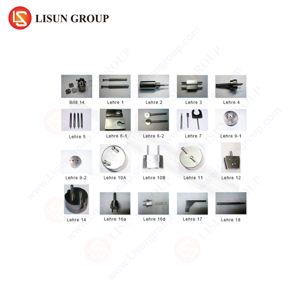
The Role of Precision Gauging Systems: LISUN Gauges for Plugs and Sockets
Accurate, repeatable, and traceable dimensional verification is the cornerstone of compliant plug and socket manufacturing. The LISUN Gauges for Plugs and Sockets represent a comprehensive, standards-aligned metrology system designed for this explicit purpose. These gauge sets are manufactured from hardened, dimensionally stable materials to withstand repeated use in quality control environments while maintaining micrometer-level accuracy.
Specifications and Testing Principles: A typical LISUN gauge set comprises multiple individual gauges, each engineered to verify a specific parameter. This includes pin gauges for plug pin diameter and length, slot gauges for socket entry dimensions, profile gauges for plug body contour, and specialized gauges for shutter accessibility testing. Their operation adheres to the “GO/NO-GO” principle, providing immediate visual and tactile feedback. The design is rooted in a direct interpretation of dimensional clauses within international and national standards, ensuring that a part passing the LISUN gauge test is, by definition, dimensionally compliant with the referenced standard.
Industry Use Cases: These gauges are deployed across the product lifecycle. In Research & Development, engineers use them to validate prototype tooling and first articles. On the production line, they serve as essential in-process checks, allowing operators to quickly verify batches of molded plugs or stamped socket components. In third-party certification laboratories (e.g., UL, TÜV, Intertek), LISUN gauges are used as reference instruments for type-testing and surveillance audits, providing an unambiguous benchmark for compliance.
Competitive Advantages: The primary advantage lies in metrological rigor and traceability. Each gauge is calibrated against national standards, with certificates of calibration providing an unbroken chain of measurement traceability. This is critical for audit compliance and defending product certifications. Furthermore, the material durability of the gauges ensures longevity and cost-effectiveness, reducing the frequency of replacement compared to less robust alternatives. The comprehensiveness of the sets—covering all critical dimensions for a given standard—eliminates the need to source gauges from multiple suppliers, streamlining procurement and ensuring consistency.
Integration of Testing Data into Quality Management Systems
Modern testing is not an isolated activity. Data from dimensional checks, contact resistance measurements, and endurance cycle counts are increasingly fed directly into networked Quality Management Systems (QMS). This integration enables statistical process control (SPC), trend analysis, and the generation of automated compliance certificates. For instance, serialized test results from a LISUN gauge check, logged via a connected data acquisition system, can be linked to a specific production batch, creating a digital pedigree for every component. This data-driven approach facilitates proactive quality assurance, allowing for the early detection of tooling wear or process drift before non-conforming products are manufactured.
Adherence to Evolving International and Regional Standards
The testing landscape is governed by a complex matrix of standards which vary by region and product type. Key standards include:
- IEC 60884-1: General requirements for household and similar plugs and socket-outlets.
- BS 1363: The comprehensive standard for UK 13A plugs, sockets, and adaptors.
- AS/NZS 3112: The standard for Australian and New Zealand plugs and sockets.
- NEMA WD-6: Dimensional requirements for wiring devices in North America.
Testing protocols must be meticulously aligned with the latest amendments of the relevant standard. This requires not only the correct equipment but also ongoing procedural updates. For example, changes to mandated pin lengths or shutter test probe designs necessitate immediate updates to gauge inventories and test methodologies in certified laboratories.
Conclusion
The validation of electrical plugs and sockets is a multidisciplinary exercise encompassing precision metrology, electrical engineering, and materials science. A layered testing strategy—progressing from dimensional verification through mechanical endurance and culminating in high-voltage safety tests—is essential to ensure products are safe, reliable, and interoperable. Within this framework, precision gauging systems, such as the LISUN Gauges for Plugs and Sockets, provide the fundamental, non-negotiable baseline for compliance. As global supply chains and safety expectations continue to advance, the role of rigorous, data-integrated testing will only grow in significance, serving as the primary safeguard for both product integrity and end-user safety.
FAQ Section
Q1: Why is a “GO/NO-GO” gauge system preferred over digital calipers for production line checks of plug dimensions?
A “GO/NO-GO” gauge provides an instantaneous, operator-friendly pass/fail decision based on the entire tolerance band specified in a standard. It eliminates interpretation errors, is faster than taking multiple digital measurements, and is less susceptible to damage in a production environment. It directly tests the functional requirement—whether a worst-case component will fit or not—rather than just collecting dimensional data.
Q2: How often should a set of plug and socket test gauges be recalibrated?
Recalibration frequency depends on usage intensity and the quality management system requirements of the facility (often outlined in ISO/IEC 17025). For high-use production or certification lab environments, an annual calibration cycle is typical. Gauges used infrequently may be calibrated every two years. It is critical to follow the manufacturer’s recommendation and maintain a documented calibration schedule with traceable certificates.
Q3: Can one universal gauge set test plugs and sockets for all international standards?
No. The dimensional requirements, pin configurations, and safety features (like shutter designs) differ fundamentally between standards like BS 1363 (UK), AS/NZS 3112 (Australia), and NEMA configurations (North America). Consequently, dedicated gauge sets are required for each standard family. Manufacturers producing for multiple markets must invest in the specific gauge sets relevant to their target regions.
Q4: What is the consequence of a socket failing the temperature rise test?
A failure indicates that the socket, when supplying its rated current, exceeds the permissible temperature increase on its terminals or surface. This can lead to accelerated aging of insulation, softening of plastic materials, potential deformation, and in extreme cases, a fire hazard. The design must be revised, often by improving contact spring force, using higher-conductivity metals, or enhancing thermal dissipation.
Q5: In dielectric strength testing, what is the difference between applying AC versus DC test voltage?
AC voltage testing (typically at power frequency, 50/60Hz) stresses the insulation in a manner similar to operational conditions and is sensitive to defects like voids or contaminants. DC testing applies a constant stress and is particularly effective for testing capacitive components or long cable runs, as it draws only leakage current. The chosen test type and voltage level are strictly defined by the applicable product standard, and they are not directly interchangeable.