


A Comprehensive Analysis of Electrical Safety Testing: Principles, Standards, and Flammability Assessment
Electrical safety testing constitutes a critical, non-negotiable pillar in the design, manufacturing, and certification of virtually all electrotechnical products. Its primary objective is the prevention of hazards that could lead to electric shock, fire, mechanical injury, or excessive radiation. This systematic evaluation ensures that products not only function as intended under normal operating conditions but also fail in a predictable, safe manner under foreseeable fault conditions. The scope of testing is vast, encompassing dielectric strength, insulation resistance, earth continuity, leakage current, and—of paramount importance for fire risk mitigation—flammability assessment. This article provides a detailed examination of these testing domains, with particular emphasis on the methodologies and apparatus used for evaluating the resistance of materials to ignition, specifically through needle flame test procedures.
Fundamental Tenets of Dielectric and Insulation Testing
The integrity of electrical insulation is the first line of defense against electric shock and short-circuit faults. Two principal tests validate this integrity: Dielectric Withstand (Hi-Pot) and Insulation Resistance (IR) testing.
Dielectric Withstand testing applies a high voltage, significantly above normal operating levels, between live parts and accessible conductive surfaces. The test voltage, defined by standards such as IEC 60335-1 (household appliances) or IEC 60601-1 (medical equipment), is maintained for a specified duration—typically one minute for type testing. The pass criterion is the absence of dielectric breakdown, indicated by a leakage current below a prescribed threshold. This test verifies that the insulation system possesses sufficient margin to withstand transient overvoltages, such as those from switching events or lightning surges on mains inputs.
Insulation Resistance measurement, conversely, employs a DC voltage (usually 500V DC) to quantify the ohmic resistance of the insulation. Measured in megohms (MΩ), this value indicates the quality and cleanliness of the insulating material. A low IR reading can signal contamination, moisture ingress, or degradation of the insulating polymer, potentially leading to increased leakage currents and eventual failure. For cable and wiring systems, this test is indispensable for ensuring long-term reliability in varied environmental conditions.
Earth Bonding and Protective Conductor Continuity Verification
For Class I equipment (devices with a protective earth terminal), a robust, low-resistance connection between any accessible conductive part and the earth pin of the mains plug is essential. The Earth Bonding test verifies this by injecting a high current, often 25A or more, from the earth point to all exposed conductive surfaces. The resulting voltage drop is measured, and resistance is calculated. Standards mandate a maximum resistance, frequently 0.1Ω or 0.2Ω, to ensure that in the event of a fault where a live conductor contacts the enclosure, sufficient current will flow to rapidly operate the circuit’s protective device (fuse or breaker), thereby removing the hazardous voltage. This test is critical for industrial control systems, large household appliances like washing machines, and metal-bodied office equipment.
Quantifying Touch and Patient Leakage Currents
Leakage current measurement assesses the small, inevitable current that flows through or across insulation under normal operating conditions. Excessive leakage poses a shock hazard. Testing involves powering the equipment at 110% of rated voltage and measuring current using a network that simulates human body impedance, as defined in IEC 60990.
Two primary types are measured: Touch Current (for general equipment) and Patient Leakage Current (for medical devices applied to a patient). For medical devices per IEC 60601-1, limits are exceptionally stringent, often in the microampere range, due to the direct patient connection and potential for compromised skin impedance. Telecommunications equipment and information technology gear, governed by IEC 62368-1, also have specific leakage limits to ensure safety for operators.
The Critical Role of Flammability Testing in Fire Hazard Mitigation
While electrical tests guard against shock, flammability testing addresses the potentially catastrophic risk of fire. Fault conditions—such as overheated components, arcing connections, or failed semiconductors—can act as ignition sources. If these sources impinge on nearby materials, such as plastic enclosures, internal barriers, or wire insulation, they must not propagate flame.
Numerous standardized tests exist to classify material flammability, including the Glow-Wire Test (IEC 60695-2-11), Horizontal/Vertical Flame Tests (UL 94), and the Needle-Flame Test (IEC 60695-2-2). The selection depends on the simulated fault condition and the product standard’s hazard-based philosophy.
The Needle-Flame Test is specifically designed to simulate the effect of a small flame that may result from a fault condition within equipment, such as an overloaded resistor or a poor connection. It is a severity-based test applied to materials and sub-assemblies likely to be exposed to such small ignition sources. Its application spans virtually every industry utilizing electrical components.
Methodology and Apparatus of the Needle-Flame Test
The test procedure, standardized in IEC 60695-2-2, involves applying a defined needle flame from a specified burner to the test specimen for a predetermined period (e.g., 30 seconds). The flame is produced by combusting butane gas through a 0.5mm ± 0.1mm diameter nozzle. After flame application, observations are made for:
- Duration of specimen flaming and glowing.
- Whether flaming droplets or particles occur.
- The extent of damage (burned length) from the original point of impingement.
Pass/fail criteria are typically defined in the end-product standard. For instance, a standard may require that flames self-extinguish within 30 seconds after removal of the test flame and that burning does not spread beyond a specified mark. This test is crucial for evaluating non-metallic parts in switches, sockets, connector housings, and internal supports within automotive electronics, aerospace components, and consumer electronics.
The LISUN ZY-3 Needle Flame Test Apparatus: Specifications and Operational Fidelity
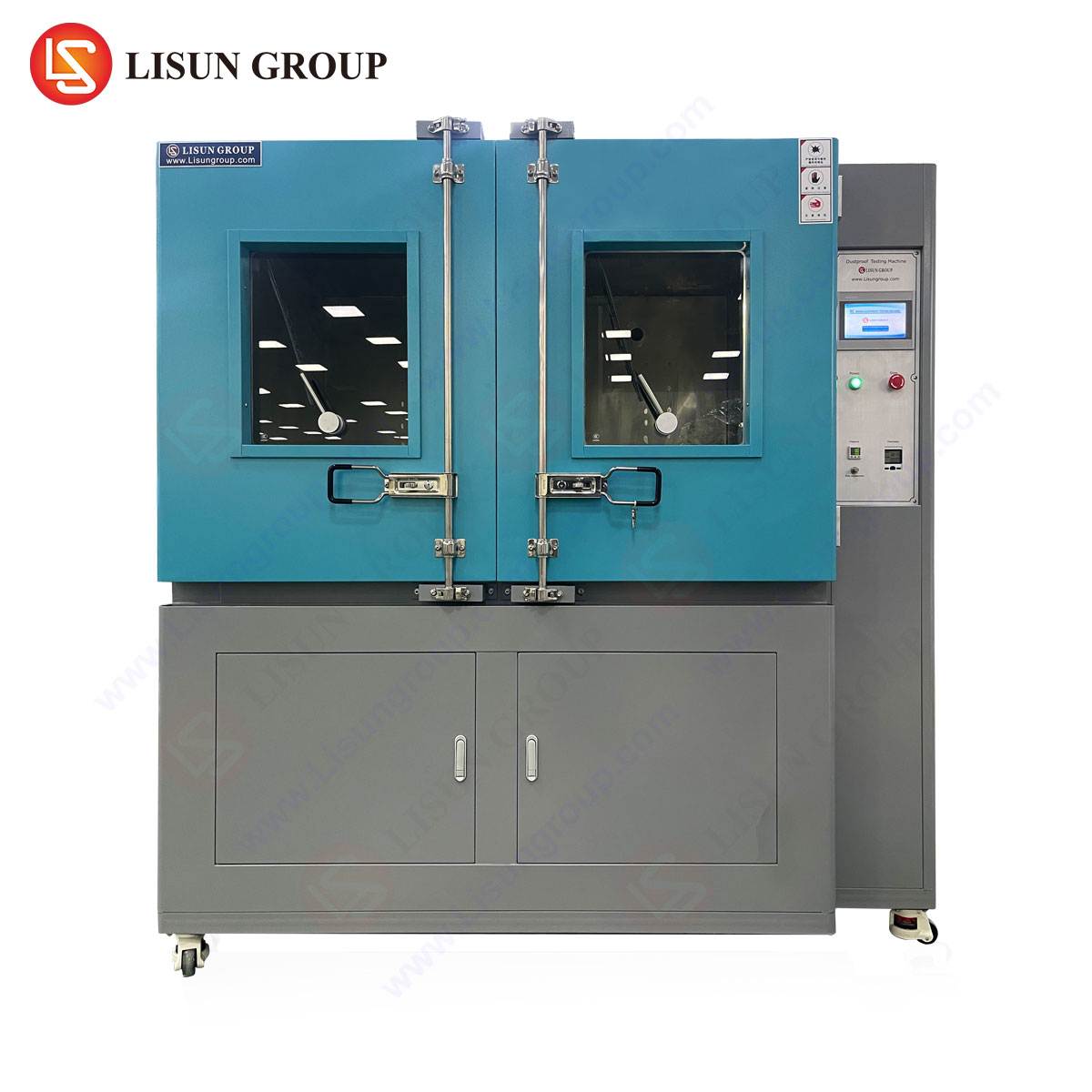
To execute the Needle-Flame Test with repeatable, standards-compliant accuracy, specialized apparatus is required. The LISUN ZY-3 Needle Flame Test Chamber represents a dedicated solution engineered to meet the exacting requirements of IEC 60695-2-2, GB/T 5169.5, and related standards.
The apparatus is constructed with a stainless steel main body and tempered glass observation windows, providing durability and clear visibility. Its core function is the precise control and application of the needle flame. The integrated burner assembly allows for fine adjustment of the flame height, which is calibrated to a reference mark of 12mm ± 1mm using a calibrated gauge. A key feature is the automated timing sequence: the test duration (flame application time) and post-application observation period are controlled via a digital timer with 0.1-second resolution, eliminating human timing error.
Key Technical Specifications of the LISUN ZY-3:
- Flame Height Adjustment Range: 12mm ± 1mm (calibrated).
- Test Duration Timer: 0~999.9s (digital, settable).
- Observation Timer: 0~999.9s (digital, automatic start upon flame removal).
- Burner Nozzle Diameter: Ø0.5mm (meeting standard specification).
- Chamber Dimensions: Sufficient to accommodate standard specimens and allow for normal air circulation during testing.
- Gas Supply: Utilizes high-purity butane (≥95% purity) to ensure consistent flame temperature and characteristics.
- Safety Features: Includes integrated ventilation and fume extraction ports to remove combustion products.
The testing principle revolves around consistent simulation. The specimen is mounted on a adjustable support within the chamber. The burner, fixed at a 45-degree angle as per many test configurations, is brought into position. Upon initiation, the precisely controlled flame is applied to the predetermined point on the specimen. The digital timers ensure strict adherence to the application period. After flame removal, the observation timer automatically records the duration of any sustained flaming or glowing. This automated, enclosed process ensures not only repeatability essential for laboratory accreditation, but also operator safety by containing the test and its byproducts.
Industry-Specific Applications for Needle Flame Compliance
The applicability of needle flame testing is ubiquitous across the electrotechnical landscape.
- Household Appliances & Electrical Components: Internal plastic parts near series-wound motor commutators, terminal blocks, or control boards in food processors, power tools, and switches/sockets must resist ignition from arc-generated particles.
- Automotive Electronics: Under-hood components, connector bodies, and sensor housings are subjected to potential short-circuit events. Compliance with automotive-specific adaptations of flame tests is often mandatory.
- Lighting Fixtures: Particularly LED drivers and plastic diffuser holders in close proximity to driver electronics, where component failure could generate a localized hot spot.
- Medical Devices: For non-life-supporting equipment, internal plastic materials that could be exposed to faults in power supplies or heating elements require assessment.
- Aerospace & Aviation Components: The extreme consequence of fire in these applications makes flammability testing of wire insulation, connector housings, and interior panel materials a critical part of DO-160 or similar compliance.
- Telecommunications & Industrial Control Equipment: PCB materials, enclosures for remote terminal units, and plastic cable management parts within racks and cabinets are common test subjects.
Comparative Advantages of Dedicated Needle Flame Test Equipment
Utilizing a purpose-built apparatus like the LISUN ZY-3 offers distinct advantages over improvised or multi-function test setups. Standard Compliance is foremost; the design ensures alignment with the dimensional, timing, and flame parameter mandates of the relevant standards, which is a fundamental requirement for test reports submitted to certification bodies (UL, TÜV, Intertek, etc.). Measurement Repeatability and Reproducibility (R&R) is significantly enhanced by automated timing, a stable burner platform, and a controlled chamber environment, reducing inter-operator variability. Operational Safety is engineered into the system via flame containment, fume extraction, and the use of stable, calibrated components. Finally, Testing Efficiency is improved through dedicated setup, clear observation, and reliable instrumentation, streamlining the qualification process for R&D and quality assurance laboratories.
Integration into a Holistic Safety Testing Regime
It is imperative to view needle flame testing not as an isolated activity, but as an integral component of a comprehensive safety engineering strategy. Its results inform material selection and mechanical design—for example, specifying a material with a better flame class, adding internal metallic shields, or increasing creepage distances around potential ignition sources. The test often follows other stress tests, such as humidity conditioning or overload tests, to evaluate safety under worst-case scenarios. Data from flammability tests feed directly into hazard-based safety engineering processes outlined in modern standards like IEC 62368-1, helping manufacturers identify and mitigate fire-related energy hazards systematically.
Conclusion
Electrical safety testing is a multifaceted discipline grounded in international standards and empirical verification. Flammability assessment, particularly via the needle flame test, addresses a fundamental hazard with severe potential consequences. The employment of precise, reliable, and standards-conforming apparatus is not merely a matter of regulatory compliance, but a fundamental aspect of responsible product design and manufacturing. By rigorously applying these tests—from dielectric strength to flame resistance—manufacturers across all sectors can substantiate the safety of their products, protect end-users, and mitigate the risks associated with the ubiquitous use of electrical energy in modern technology.
FAQ Section
Q1: What is the primary difference between the Needle-Flame Test (IEC 60695-2-2) and the Glow-Wire Test (IEC 60695-2-11)?
A1: The tests simulate different fault conditions. The Needle-Flame Test simulates the effect of a small, direct flame from an ignition source like an overheated component or electrical arc. The Glow-Wire Test simulates the effect of an overheated or glowing element (like a resistor or bad connection) coming into contact with or being surrounded by a material. The ignition source, temperature profile, and application method differ fundamentally between the two tests.
Q2: For the LISUN ZY-3, what is the required purity of the butane gas, and why is it specified?
A2: The standard recommends, and the LISUN ZY-3 operational manual specifies, the use of butane gas with a purity of at least 95%. This requirement ensures consistent combustion characteristics, including flame temperature and stability. Lower-purity gas containing significant propellant or other hydrocarbons can alter the flame’s thermal output and geometry, introducing variability that could compromise the repeatability and validity of test results.
Q3: Can the LISUN ZY-3 be used to test finished products, or only material samples?
A3: While often used on standardized material plaques for comparative ranking, the needle flame test as per IEC 60695-2-2 is intended to be applied to “end products, sub-assemblies, components, and electrical parts.” Therefore, the LISUN ZY-3 can and should be used to test actual parts in their final form—such as a switch housing, a section of wiring harness, or a PCB assembly—as installed in the equipment, provided they fit within the test chamber and the flame can be applied to the relevant area.
Q4: How often should the flame height of the apparatus be calibrated, and what is the procedure?
A4: Flame height should be verified before each test session or series of tests. The procedure involves adjusting the gas flow to produce a stable flame, then using a calibrated height gauge (typically a metal block with a 12mm ± 0.5mm step) placed adjacent to the flame. The flame tip should align with the gauge mark. Frequent verification is necessary as nozzle condition, gas pressure, and ambient drafts can affect the flame.
Q5: In which industry standards, besides IEC 60695-2-2, is the needle flame test methodology referenced?
A5: The needle flame test is incorporated by reference in numerous end-product safety standards. Key examples include IEC 60335-1 (Household appliances), IEC 60598-1 (Lighting fixtures), IEC 60950-1/62368-1 (IT/AV equipment), IEC 60601-1 (Medical equipment), and various automotive (ISO 6722) and aerospace (DO-160) component specifications. The test criteria (application time, pass/fail conditions) are defined within the specific clause of each end-product standard.