


A Comprehensive Framework for Electrical Socket Safety Standards: Design, Testing, and Compliance Verification
Introduction to Socket Safety and Standardization Imperatives
The ubiquitous electrical socket, a critical interface between fixed installations and portable equipment, represents a nexus of significant electrical hazard. Its safety performance is non-negotiable, governed by a complex matrix of international, regional, and national standards that dictate every aspect of design, material selection, and mechanical function. These standards—such as IEC 60884-1, BS 1363, AS/NZS 3112, and NEMA WD-6—are not arbitrary prescriptions but are derived from rigorous risk analysis of historical failure modes, including electric shock, fire initiation, and mechanical degradation. The primary objectives are to ensure user protection through fundamental principles: assured earthing continuity, prevention of access to live parts, secure contact engagement to mitigate overheating, and robust mechanical integrity to withstand insertion cycles and environmental stress. Compliance with these standards is a legal and ethical mandate for manufacturers, requiring a systematic approach to design validation and production line testing. This article delineates the core safety parameters for plugs and sockets, explores the testing methodologies mandated for compliance, and examines the role of advanced instrumentation in ensuring adherence to these critical safety protocols.
Fundamental Design Principles for Shock and Fire Prevention
The foundational safety architecture of a socket is engineered to address two paramount risks: electric shock and thermal runaway leading to fire. Shock protection is primarily achieved through the physical configuration of the socket outlets and the plug pins. Standards meticulously define pin dimensions, spacing (creepage and clearance distances), and shielding. A key principle is the “shuttered outlet” design, mandated in many standards like BS 1363, which employs internal mechanical shutters that are only opened by the simultaneous insertion of the line and neutral pins, preventing the insertion of foreign objects into a live contact. Furthermore, the sequence of mating is critical: earth pins are typically longer to ensure protective earth connection is established before line and neutral contacts are made, and broken last upon withdrawal.
Fire prevention is intrinsically linked to the quality of the electrical contact. Poor contact between plug pin and socket receptacle leads to a high-resistance connection. According to Joule’s Law (P = I²R), this elevated resistance results in localized heating proportional to the square of the current. Over time, this can cause insulation degradation, contact oxidation (further increasing resistance), and ultimately ignition of surrounding materials. Standards combat this by specifying stringent requirements for contact materials, contact normal force, and the mechanical durability of the socket. Contact materials, often phosphor bronze or beryllium copper alloys, must maintain spring properties and low oxidation over thousands of insertion cycles. The contact normal force—the pressure exerted by the socket contact on the plug pin—is a critical parameter; too low a force increases contact resistance, while excessively high force accelerates mechanical wear and makes insertion difficult for users.
Mechanical and Environmental Durability Requirements
A socket must perform safely not only when new but throughout its operational lifespan, which involves repeated mechanical stress and exposure to environmental variables. Mechanical endurance testing, often called “insertion-withdrawal” or “durability” testing, subjects the socket to a specified number of cycles (commonly 10,000 to 40,000 cycles) using a standardized test probe. This evaluates the socket’s ability to maintain electrical continuity, contact force, and insulation resistance without mechanical failure. The test apparatus must apply a specific insertion/withdrawal force and rate to simulate real-world use.
Environmental stress testing assesses performance under non-ideal conditions. Damp heat cycling tests (e.g., 40°C, 93% relative humidity) evaluate insulation integrity and the propensity for tracking—the formation of conductive paths on insulation surfaces. Resistance to heat is verified by a ball pressure test on insulating parts, ensuring materials do not deform excessively at elevated temperatures. Furthermore, impact tests using standardized pendulums or dropping weights verify that enclosures do not fracture in ways that expose live parts or impair functionality. For outdoor or industrial sockets, additional ratings for Ingress Protection (IP codes, per IEC 60529), such as IP44 (splash-proof) or IP67 (dust-tight and immersion resistant), define the level of sealing against solids and liquids.
Quantitative Testing Parameters and Compliance Thresholds
Compliance is not subjective; it is determined by quantitative measurements against defined thresholds. Key electrical and mechanical tests include:
- Contact Resistance: Measured in milliohms (mΩ) using a low-resistance ohmmeter under a specified test current. A stable, low value (typically well below 50 mΩ for a single contact) indicates a sound connection. This measurement must remain within limits after durability testing.
- Insulation Resistance: Measured in megohms (MΩ) by applying a high DC voltage (usually 500V DC) between live parts and earth, and between live parts. Minimum values are often 5 MΩ or higher, ensuring no significant leakage paths exist through the insulation material.
- Dielectric Strength (Withstand Voltage): A high-potential (hipot) test where an AC or DC voltage (e.g., 2000V AC, 4000V DC for basic insulation) is applied for one minute without breakdown or flashover. This verifies the integrity of insulation under transient overvoltage conditions.
- Earth Continuity: For earthed sockets, the resistance from the earth pin contact to the fixed wiring terminal must be extremely low (e.g., <0.1 Ω) to ensure a low-impedance path for fault current, enabling protective devices to operate swiftly.
- Temperature Rise: Under a rated current load, the temperature increase of terminals and contacts above ambient is measured using thermocouples. Limits (often 50°K or 52°K rise) prevent thermal damage to connected cables and socket components.
Instrumentation for Verification: The Role of Specialized Test Equipment
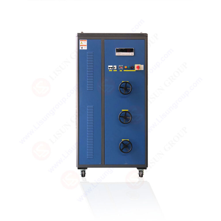
Accurate, reliable, and repeatable measurement of these parameters is impossible without sophisticated test equipment. This is where dedicated plug and socket testers, such as the LISUN Gauges for Plugs and Sockets, become indispensable tools for both quality assurance laboratories and production lines. These instruments are not simple “go/no-go” devices but precision measurement systems designed to automate and standardize compliance verification against the geometric and force-based criteria specified in standards.
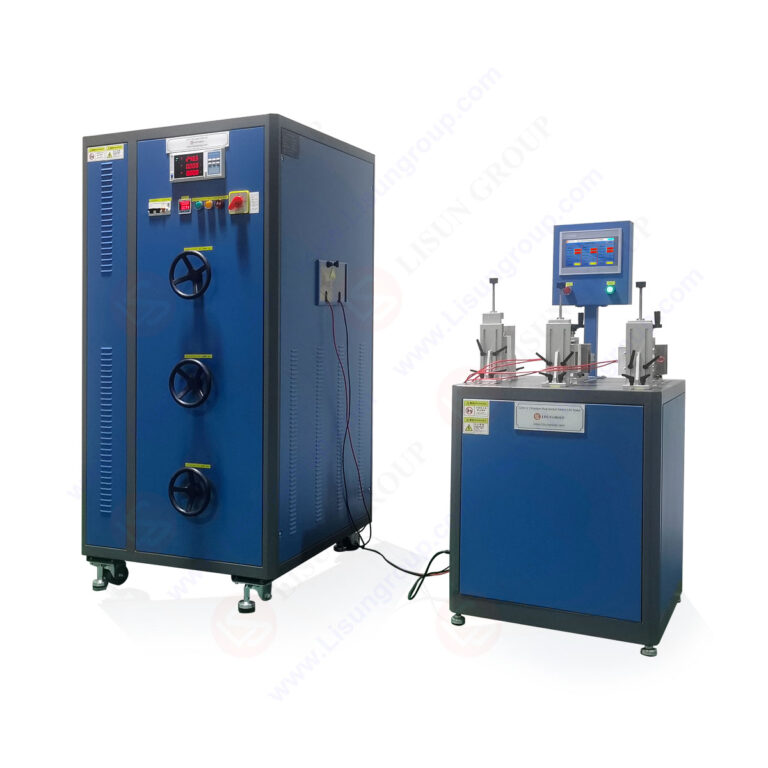
The LISUN LPSC-2 Series Plug and Socket Gauge System, for instance, embodies this principle. It comprises a suite of calibrated gauges and force measurement devices used to verify critical mechanical dimensions and forces that directly impact safety. Its operation is based on the precise application and measurement of mechanical parameters as mandated by standards like IEC 60884-1.
Testing Principles and Specifications of the LISUN Gauge System
The LISUN system’s testing principles are rooted in simulating the interaction between plug and socket with calibrated precision. Key functions include:
- Contact Engagement Force Verification: The device measures the force required to insert a standardized test pin into the socket contact. This force must fall within a specified range (e.g., 1.5N to 4.0N per pin for some standards) to ensure secure contact without excessive user effort. A digital force gauge provides an objective, numerical readout, eliminating operator subjectivity.
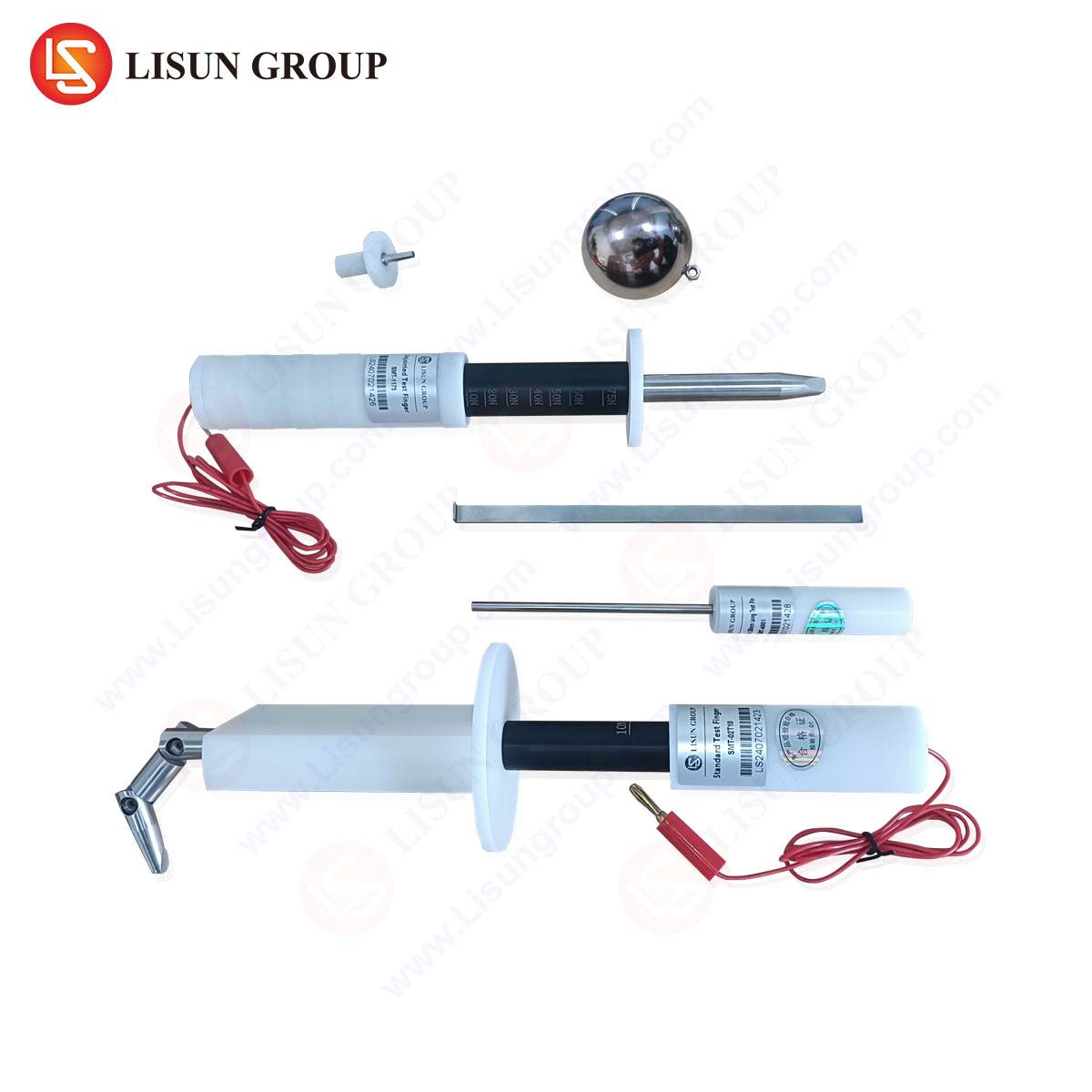
- Shutter Opening Force and Function Test: For shuttered sockets, a simulated “child probe” (a standardized pin designed to test shock protection) is applied with a measured force. The shutter must not open, or must require a force above a safe threshold (e.g., >20N). Subsequently, a correct plug gauge is used to verify the shutters open smoothly with the appropriate pin sequence.
- Pin Gauge Dimensional Verification: A set of “GO/NO-GO” gauges, manufactured to the extreme dimensional tolerances of the standard, are used to check socket entry dimensions, pin apertures, and the size of shutters. A “GO” gauge must fit freely, while a “NO-GO” gauge must not enter, ensuring compatibility with compliant plugs and rejection of non-compliant or hazardous objects.
- Withdrawal Force Measurement: After insertion, the force required to withdraw the test pin is measured, ensuring the socket maintains adequate grip on the plug to prevent accidental disconnection but does not retain it so firmly as to cause damage.
These measurements are typically conducted within a controlled test station that may include motorized actuators for repeatable insertion speed and angle, data logging software for traceability, and configurable pass/fail limits aligned with target standards.
Industry Application in Quality Assurance and Production
The application of such gauge systems spans the product lifecycle. In Research & Development, engineers use them to validate prototype designs against target standards before formal certification. In production, they are deployed for Statistical Process Control (SPC) and Acceptance Quality Limit (AQL) sampling. Regular checks of contact force, shutter operation, and dimensional accuracy on the production line provide real-time feedback, allowing for immediate correction of tooling wear or assembly drift before non-conforming products are manufactured in volume.
For certification bodies and testing laboratories, the LISUN gauges serve as reference equipment for conducting type tests and surveillance audits. Their calibration traceability to national metrology institutes (NMI) is essential for maintaining the integrity of the test results upon which certification marks (CE, UL, CSA, etc.) are granted. In aftermarket and regulatory surveillance, authorities use such equipment to verify the compliance of products already on the market, ensuring ongoing adherence to safety standards.
Competitive Advantages of Precision Gauge Systems
The competitive advantage conferred by a system like the LISUN LPSC-2 lies in its metrological rigor, operational efficiency, and data integrity. Unlike manual feeler gauges or subjective hand-force tests, digital force measurement eliminates operator variance, producing auditable, numerical data. Automated test sequences reduce human error and increase throughput in production environments. The modular design, often supporting gauges for multiple international standards (UK, EU, AU, US, etc.), offers flexibility for manufacturers producing for global markets. Furthermore, integrated software capabilities enable the creation of detailed test reports, essential for certification dossiers and quality management system (ISO 9001) audits. This transforms safety compliance from a qualitative checkpoint into a quantitatively managed, data-driven process.
Integration with Broader Electrical Safety Testing Regimes
It is crucial to view dimensional and force testing not in isolation but as an integral component of a holistic safety testing regime. A socket that passes gauge tests must subsequently, or concurrently, pass the electrical tests previously described—insulation resistance, dielectric strength, temperature rise, and durability. The synergy is clear: a socket with correctly specified contact force (verified by gauge) will inherently exhibit lower and more stable contact resistance during electrical load testing. A socket with properly functioning shutters (verified by gauge) will inherently pass the probe tests within the dielectric strength assessment. Therefore, the gauge system provides the foundational mechanical validation that enables subsequent electrical tests to be meaningful and predictive of real-world safety.
Conclusion: The Unbroken Chain of Safety Assurance
The safety of an electrical socket is the culmination of intentional design, specification-compliant manufacturing, and rigorous verification. International standards provide the blueprint, but it is through precise, repeatable testing—enabled by specialized instrumentation like the LISUN Gauges for Plugs and Sockets—that compliance is objectively demonstrated and maintained. As socket designs evolve with smart technologies and higher power delivery requirements (e.g., for electric vehicle charging), the underlying principles of mechanical integrity, electrical contact quality, and user protection remain constant. The industry’s reliance on advanced, calibrated test equipment ensures that these principles are upheld, maintaining the unbroken chain of safety assurance from the factory to the final installation.
FAQ Section
Q1: How often should plug and socket gauge systems be calibrated in a production environment?
Calibration frequency depends on usage intensity and the requirements of the quality management system. For high-volume production lines where gauges are in constant use, an annual calibration cycle is typical, with intermediate checks using master reference artifacts. The calibration must be traceable to a national metrology institute to ensure measurement integrity for compliance purposes.
Q2: Can one gauge system be used to test sockets designed for different international standards?
Yes, modular gauge systems like the LISUN LPSC-2 are often designed with this flexibility. They utilize interchangeable test probes and pin sets that are machined to the specific dimensional tolerances of different standards (e.g., BS 1363, CEE 7, AS/NZS 3112). The force measurement unit and control system remain universal, while the application-specific gauge kits are swapped as needed.
Q3: What is the significance of measuring both insertion and withdrawal force?
Insertion force ensures the socket does not present undue difficulty for the user, which could lead to improper insertion or damage. Withdrawal force verifies the socket’s retention capability, ensuring a plug remains securely connected under normal conditions but can be removed without excessive strain on the cord. Both parameters are critical for user experience and long-term contact reliability.
Q4: In addition to production, where else are these gauge systems utilized?
Beyond manufacturing QA, they are essential in third-party certification laboratories for type-testing new products, in national standards bodies for developing and refining test methods, and by market surveillance authorities to verify the compliance of products obtained from retail channels. They are also used by large purchasers and specifiers to conduct incoming inspection of sourced components.
Q5: How does automated gauge testing integrate with a smart factory or Industry 4.0 setup?
Modern gauge systems can be equipped with industrial communication protocols (e.g., Ethernet/IP, Modbus TCP) to feed measurement data directly into a Manufacturing Execution System (MES) or central data lake. This enables real-time SPC dashboards, predictive maintenance alerts for tooling based on force trend analysis, and full digital traceability where every tested unit’s mechanical performance data is linked to its serial number.