


Comprehensive Analysis of Electrical Socket Testers: Principles, Standards, and Advanced Instrumentation
Electrical socket testers represent a critical class of diagnostic instruments within the broader domain of electrical safety and compliance verification. These devices serve as the first line of defense in identifying potentially hazardous wiring conditions in alternating current (AC) power outlets, thereby mitigating risks of electric shock, equipment damage, and fire. This technical article provides a detailed examination of socket tester operational principles, international standards governing their use and performance, and the evolution of the technology from simple neon-lamp indicators to sophisticated, data-driven measurement systems. A particular focus is placed on advanced professional-grade equipment, exemplified by the LISUN Gauges for Plugs and Sockets series, which bridges the gap between basic fault detection and quantitative, standards-aligned verification.
Fundamental Operational Principles and Fault Detection Methodology
At its core, a socket tester operates by interfacing directly with the contacts of a power outlet—typically Line (Live), Neutral, and Protective Earth (Ground). The internal circuitry is designed to evaluate the continuity, polarity, and integrity of these connections through a series of passive and active tests. The most rudimentary testers utilize a network of resistors and neon lamps or light-emitting diodes (LEDs) to create current paths and provide a visual fault indication via a specific pattern of illuminated lights.
The fundamental wiring conditions detected include:
- Correct Wiring: Indicates proper connection of Line, Neutral, and Earth terminals.
- Live/Neutral Reverse: A condition where the Line and Neutral conductors are interchanged at the socket. While some equipment may still operate, this compromises safety by placing the switch and fuse on the neutral side, leaving equipment internally energized when switched off.
- Live/Earth Reverse: A severe hazard where Line and Earth are swapped. This can result in the equipment casing becoming live at full mains potential.
- Open Circuit Neutral or Earth: A missing or broken connection for the respective conductor.
- No Earth Connection: Absence of a functional protective earth, rendering Class I (earthed) equipment unsafe.
More advanced instruments incorporate microcontrollers and precision measurement circuits to perform quantitative analyses. These can measure actual voltage between contacts, earth loop impedance (often via a simulated load test), and the presence of nominal voltage on the earth pin, which indicates a dangerous Neutral-Earth fault upstream. The interpretation of results, even on basic models, is strictly defined by manufacturer instructions and must be cross-referenced with the specific socket configuration (e.g., NEMA 5-15, BS 1363, CEE 7/4).
International Standards and Regulatory Compliance Frameworks
The design, functionality, and safety of socket testers themselves are governed by a suite of international standards. Compliance with these standards is not merely a mark of quality but a prerequisite for reliable and safe operation. Key standards include:
- IEC 61010-1: Safety requirements for electrical equipment for measurement, control, and laboratory use. This standard dictates essential constructional requirements for insulation, creepage, clearance, and mechanical integrity.
- IEC 61557-1: Electrical safety in low voltage distribution systems up to 1,000 V AC and 1,500 V DC – Equipment for testing, measuring or monitoring of protective measures. This overarching standard defines general requirements for testing equipment.
- IEC 61557-6: Specifically addresses equipment for testing the effectiveness of protective measures by measuring loop impedance. Professional socket testers with earth loop measurement functionality must conform to this standard, which stipulates accuracy classes and test conditions.
Furthermore, the testers are designed to evaluate installations against national wiring regulations, such as the NEC (NFPA 70) in the United States, BS 7671 in the United Kingdom, and the IEC 60364 series internationally. A competent tester does not merely indicate a fault; it provides diagnostic information that an electrician can action within the framework of these regulations.
Evolution from Basic Indicators to Metrological Instruments
The historical progression of socket tester technology mirrors advancements in electronics miniaturization and digital processing. Early passive testers provided a binary “safe/unsafe” output with limited diagnostic granularity. The integration of microcontrollers enabled sequential testing, LCD readouts, and the ability to measure and display real voltage values. The current state of the art involves instruments that perform automated test sequences, store results, and offer connectivity for data logging and report generation.
This evolution has created distinct product tiers:
- Consumer-Grade Indicative Testers: Low-cost, portable devices for basic fault finding. They are suitable for quick checks but lack measurement precision and comprehensive fault coverage.
- Professional Diagnostic Testers: Incorporate voltage measurement, earth continuity checks (often with a >200mA test current to meet regulatory thresholds), and detection of borrowed neutrals or shared earths.
- Laboratory and Manufacturing Verification Systems: High-precision instruments used for design validation, production line testing of plugs and sockets, and compliance auditing. These systems provide traceable, quantitative data against stringent tolerances.
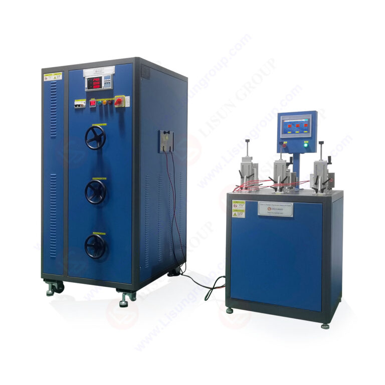
LISUN Gauges for Plugs and Sockets: A Paradigm of Precision Verification
Occupying the apex of professional and laboratory-grade verification is the LISUN Gauges for Plugs and Sockets product line. These instruments transcend basic fault detection, serving as calibrated gauges for the dimensional, mechanical, and electrical verification of plug and socket connectors themselves, in addition to live installation testing. Their primary application is within manufacturing quality control, certification laboratories, and standards institutions, where absolute measurement certainty is required.
Core Testing Principles and Specifications:
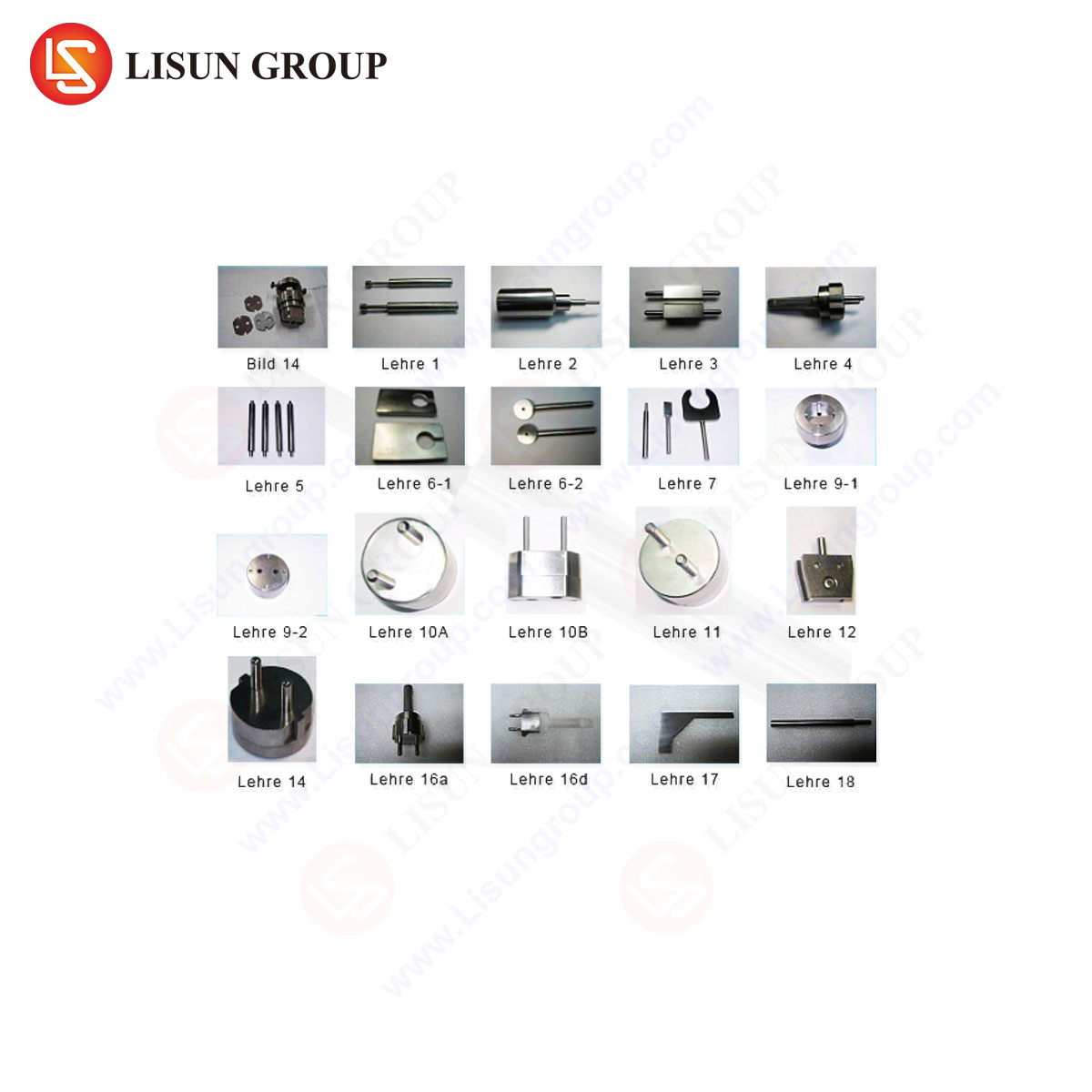
The LISUN system operates on a principle of comparative measurement against master reference gauges and absolute electrical testing. It typically consists of a main control unit and a series of interchangeable, precision-machined test probes (gauges) conforming to the dimensional templates specified in standards like IEC 60884-1 (for plugs and socket-outlets for household use). Key specifications and capabilities include:
- Dimensional Verification: Utilizes “GO/NO-GO” gauges to check critical dimensions of plug pins and socket-outlet receptacles—pin thickness, width, length, span, and aperture sizes. This ensures mechanical interoperability and safety.
- Contact Force Measurement: Measures the insertion and withdrawal force of plugs, verifying that socket contacts provide adequate grip (to prevent overheating) without excessive insertion force.
- Electrical Load Testing: Applies a calibrated resistive or resistive-inductive load to the socket under test to verify temperature rise under load does not exceed limits stipulated in standards (e.g., a 65°C maximum temperature rise at rated current).
- Dielectric Strength (Hi-Pot) Testing: Applies a high voltage (e.g., 2,000 V AC or 2,500 V AC) between live parts and earth to verify insulation integrity.
- Earth Continuity and Touch Current: Precisely measures earth bond resistance with a high test current and measures leakage currents.
A representative specification table for a LISUN system configured for common socket types might include:
| Parameter | Specification Range | Compliance Standard Reference |
|---|---|---|
| Pin Gauge Dimensions | Tolerance ±0.01mm | IEC 60884-1, Clause 9 |
| Contact Force Measurement | 0-40 N, resolution 0.1 N | IEC 60884-1, Clause 13 |
| Electrical Load Current | 0-20A AC, programmable | IEC 60884-1, Clause 19 |
| Temperature Rise Test | K-type thermocouple, ΔT measurement | IEC 60884-1, Clause 19 |
| Dielectric Test Voltage | 0-3,000 V AC, 50/60 Hz | IEC 60884-1, Clause 17 |
| Earth Continuity Test | 0-200mΩ, 25A test current | IEC 61557-4 |
Industry Use Cases and Competitive Advantages:
The LISUN system is deployed in scenarios demanding unambiguous, standards-referenced data:
- Manufacturing Quality Assurance: On production lines for plug, socket, and power strip manufacturers to perform 100% inspection or batch sampling.
- Component Supplier Qualification: Used by OEMs to validate components from second- and third-party suppliers against contractual technical specifications.
- Standards Compliance and Certification Testing: Employed by national test houses (e.g., TÜV, UL, Intertek) to certify products before awarding safety marks (CE, UKCA, UL Listing).
- Failure Analysis and Forensic Investigation: Provides objective data in cases of product failure, electrical fires, or non-conformance disputes.
Its competitive advantages stem from its integrated, traceable approach:
- Metrological Traceability: The system is calibrated against national standards, providing an unbroken chain of measurement certainty critical for legal and regulatory acceptance.
- Comprehensive Testing Suite: It consolidates dimensional, mechanical, and electrical tests into a single, automated sequence, reducing human error and increasing throughput.
- Objective Data Output: It generates quantitative pass/fail results and detailed measurement reports, eliminating the subjectivity inherent in visual inspection or basic LED testers.
- Adaptability: With interchangeable gauge sets and configurable test profiles, a single platform can verify hundreds of different plug and socket types per international, regional, and national standards.
Integration into Broader Electrical Safety Protocols
While advanced systems like the LISUN gauges are essential for product validation, the role of the handheld socket tester in field maintenance remains indispensable. A holistic electrical safety protocol employs both: the precision gauge ensures the connector itself is manufactured to specification, and the field tester verifies the installed assembly is wired correctly within a functioning electrical system. This two-tiered approach—from factory validation to in-situ verification—forms the backbone of modern electrical safety strategies for plugs and sockets, ensuring safety from the point of manufacture through decades of service life.
Frequently Asked Questions (FAQ)
Q1: Can a basic socket tester with LED indicators verify that an earth connection is functionally adequate for safety?
No, it cannot. A basic tester typically only confirms the presence of a voltage on the earth pin relative to neutral, indicating a physical connection. It does not measure the earth loop impedance (Zs), which determines if the impedance is low enough for the protective device (circuit breaker or fuse) to operate within the required time during a fault. Verification of a functionally adequate earth requires a dedicated earth loop impedance tester or a professional-grade socket tester with that specific measurement capability.
Q2: What is the significance of a “borrowed neutral” indication on an advanced socket tester, and why is it a concern?
A “borrowed neutral” occurs when the neutral conductor for a circuit is connected via a load from another circuit, often in lighting configurations. This is a serious safety hazard because if the circuit supplying the borrowed neutral is isolated (e.g., its MCB is switched off), the neutral in the tested circuit can become energized at full mains voltage through the connected load. This creates a severe risk of electric shock to personnel working on what they believe to a de-energized circuit.
Q3: In a manufacturing context, why is contact force measurement for sockets as critical as electrical testing?
Insufficient contact force leads to a high-resistance connection between the plug pin and socket contact. Under load, this resistance causes localized heating (Joule heating, P=I²R), which can degrade insulation, oxidize contacts further increasing resistance, and potentially cause fire. Excessive force makes insertion and removal difficult for users and may cause mechanical wear. Standards define strict force limits to ensure both safety and usability throughout the product’s lifespan.
Q4: How does a laboratory-grade system like the LISUN Gauges handle testing for different international plug types?
The system is designed with a modular architecture. The main control unit houses the electrical measurement and power supply electronics. The interface to the device under test is through interchangeable, precision-machined test fixtures (gauges and probe assemblies). Each fixture is engineered to the exact dimensional specifications of a target plug or socket standard (e.g., BS 1363, AS/NZS 3112, NEMA configurations). The test software is then loaded with the corresponding test profile specifying the applicable voltage, current, force, and dimensional limits for that standard.
Q5: What is the primary purpose of the dielectric strength (hipot) test in socket verification?
The dielectric test assesses the integrity of the insulation barriers within the socket-outlet. By applying a high voltage (significantly higher than normal operating voltage) between live parts and earthed parts (and between live parts of opposite polarity), the test stresses the insulation. The absence of electrical breakdown (arcing) or excessive leakage current confirms that the insulation is sufficient to protect users from electric shock under normal conditions and foreseeable transient overvoltages.