


Ensuring Operational Integrity: A Technical Analysis of EMC Compliance and EMI Measurement
The proliferation of electronic systems across every facet of modern industry has rendered the electromagnetic (EM) spectrum a critical shared resource. The unintended generation, propagation, and reception of electromagnetic energy—collectively termed Electromagnetic Interference (EMI)—poses a significant threat to the reliability, safety, and functionality of electrical and electronic equipment. Consequently, Electromagnetic Compatibility (EMC) has evolved from a secondary design consideration to a fundamental prerequisite for market access and operational deployment. EMC signifies a device’s dual capability: to function as intended within its electromagnetic environment without introducing intolerable disturbances to other apparatus (Emissions), and to maintain its performance when subjected to disturbances originating from that same environment (Immunity). This article provides a detailed technical exposition of EMC compliance frameworks, EMI measurement methodologies, and the instrumental role of specialized test equipment, with a focused analysis on anthropomorphic simulation tools such as the LISUN Test Finger, Test Probe, and Test Pin.
The Regulatory and Standards Framework Governing EMC Compliance
EMC compliance is not a singular technical target but a complex landscape defined by international, regional, and product-specific standards. Regulatory bodies, such as the Federal Communications Commission (FCC) in the United States, the European Union through the Electromagnetic Compatibility Directive (2014/30/EU), and analogous authorities worldwide, mandate adherence to harmonized standards. These standards, developed primarily by the International Electrotechnains Commission (IEC) and the International Special Committee on Radio Interference (CISPR), establish the quantitative limits for electromagnetic emissions and the minimum test levels for immunity.
For emissions, standards such as CISPR 11 (Industrial, Scientific, and Medical equipment), CISPR 32 (Multimedia equipment), and CISPR 25 (Vehicles, boats, and internal combustion engines) define permissible radiated and conducted emission levels across specified frequency bands. Immunity standards, including the IEC 61000-4 series, prescribe test methods for phenomena like electrostatic discharge (ESD – IEC 61000-4-2), electrical fast transients (EFT – IEC 61000-4-4), surges (IEC 61000-4-5), and radiated radio-frequency fields (IEC 61000-4-3). The selection of applicable standards is intrinsically linked to the product’s intended use environment. A medical device for critical care, governed by IEC 60601-1-2, faces more stringent immunity requirements than a consumer audio device, as its failure could have direct life-safety implications. Similarly, automotive electronics, per ISO 11452 and ISO 7637 series, must withstand the harsh EM environment of a vehicle, including load dump transients and high-power mobile radio signals.
Fundamental Methodologies in Electromagnetic Interference Measurement
EMI measurement is a metrology-intensive discipline conducted within controlled environments to ensure reproducibility and accuracy. Radiated emissions are typically measured on an Open-Area Test Site (OATS) or within a semi-anechoic chamber (SAC), using calibrated antennas and a spectrum analyzer or EMI receiver scanning the relevant frequency range from 30 MHz to often 6 GHz or beyond. The Equipment Under Test (EUT) is placed on a non-conductive turntable, and antenna height is varied to identify maximum emission points. Conducted emissions, covering the 150 kHz to 30 MHz range, are measured directly on the AC or DC power lines using a Line Impedance Stabilization Network (LISN), which provides a standardized impedance and isolates the EUT from ambient noise on the mains.
Immunity testing employs threat-specific test equipment. For radiated immunity, an anechoic chamber is used to subject the EUT to controlled, uniform field strengths generated by antennas driven by high-power amplifiers. Conducted immunity tests inject disturbances directly onto cables via coupling/decoupling networks (CDNs). A critical, yet often understated, aspect of both emissions and immunity testing is the configuration and exercise of the EUT. It must be operated in a worst-case emission mode, and its performance must be monitored for degradation during immunity tests. This necessitates the use of peripherals, dummy loads, and monitoring equipment that are themselves immune and non-radiating, a significant practical challenge in complex systems like industrial control panels or telecommunications base stations.
Simulating Human Interaction: The Role of Anthropomorphic Test Probes
A distinct and vital subset of immunity testing involves simulating the effects of human interaction with accessible parts of equipment. This is not merely a safety consideration for electrical shock (covered by standards like IEC 62368-1) but also an EMC concern. The human body can act as a conduit for electrostatic discharge or an antenna that inadvertently couples electromagnetic energy into sensitive circuitry. Furthermore, accessible openings, connectors, and gaps must be assessed to ensure they do not permit contact with hazardous live parts or allow test probes to compromise safety protections. This is where specialized simulation tools, precisely engineered to replicate standardized human interactions, become indispensable.
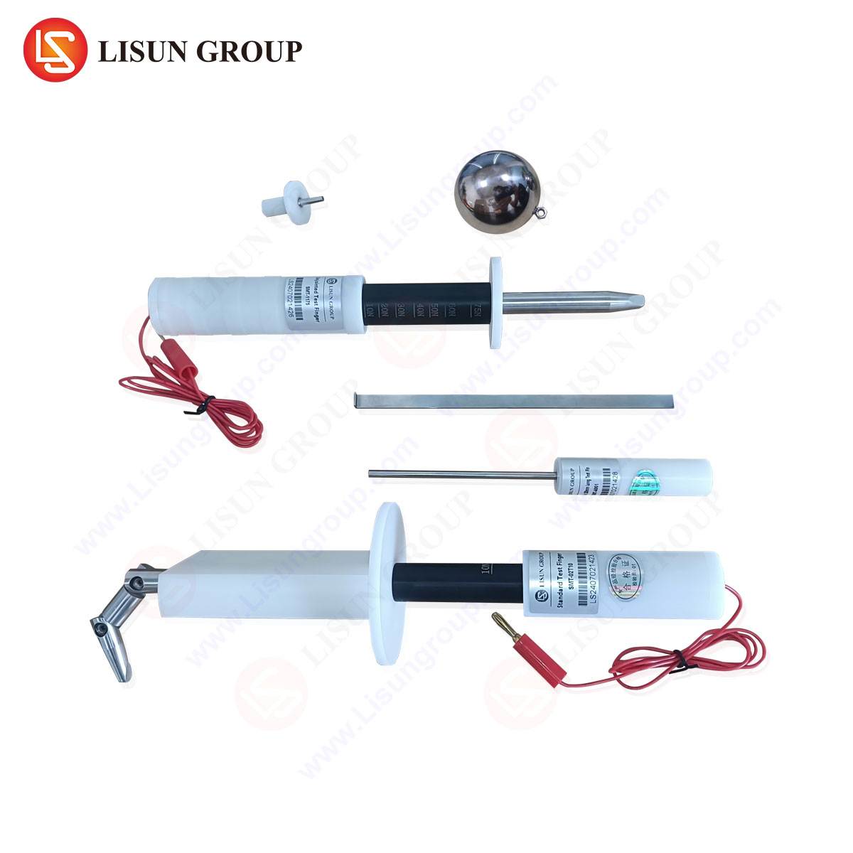
The LISUN Test Finger (IEC 61032 Probe 11 / IEC 62368-1 Figure 7) is a canonical example. It is a rigid, articulated jointed finger model constructed from materials like aluminum alloy and ABS plastic, with dimensions strictly defined to simulate the finger of a child or adult. Its primary application is the “accessibility probe test” to verify that hazardous live parts cannot be contacted through openings in enclosures of household appliances, office equipment, lighting fixtures, and consumer electronics. During testing, the probe is applied with a specified force (typically 30N ± 3N) to every potential opening. The product complies only if the probe cannot contact live parts or basic insulation. Its use is mandated in safety standards globally and is a critical step in the certification of electrical components like switches and sockets.
For smaller openings, the LISUN Test Probe (IEC 61032 Probe 13 / IEC 62368-1 Figure 9) is employed. This is a straight, rigid steel rod of 1.0 mm diameter. It is designed to probe openings that are too small for the test finger but could still pose a risk if a stiff wire or tool were inserted. Its application is widespread in the toy and children’s products industry, as well as in compact consumer electronics and small household appliances, ensuring that even narrow vents or gaps do not provide access to dangerous energy levels.
The LISUN Test Pin (IEC 61032 Probe 12 / IEC 62368-1 Figure 8) serves a similar but distinct purpose. It is a simulated finger nail or similar small, rigid object, typically a steel pin with a hemispherical end of 3mm radius. Applied with a force of 10N ± 1N, it tests for hazards accessible with a fingernail or small tool. This is particularly relevant for slots in plastic enclosures, battery compartment covers, or adjustable controls on industrial systems and automotive electronics, where a user might attempt to pry open a cover.
Table 1: Key Specifications and Applications of Anthropomorphic Test Probes
| Probe Type | Standard Reference | Key Dimensions / Material | Test Force | Primary Industry Use Cases |
| :— | :— | :— | :— | :— |
| Test Finger | IEC 61032 Probe 11 | Articulated, 75mm long, 12mm dia. joints (metal/plastic) | 30N ± 3N | Household appliances, lighting, office equipment, consumer electronics, power components. |
| Test Probe | IEC 61032 Probe 13 | Rigid steel rod, 1.0mm diameter, 100mm length. | 1N ± 0.1N | Toys, small consumer electronics, compact telecom devices, medical device housings. |
| Test Pin | IEC 61032 Probe 12 | Steel pin, 3mm radius hemispherical end. | 10N ± 1N | Automotive interior controls, industrial system interfaces, battery compartments, appliance controls. |
Integration of Probe Testing within Holistic EMC Validation
The use of the Test Finger, Probe, and Pin is not an isolated activity but is integrated into a broader safety and EMC engineering process. In the context of EMC, these tests often precede or run concurrently with immunity tests. For instance, before subjecting a household refrigerator to ESD testing, the test finger identifies all points a user might touch, which then become primary targets for ESD gun discharges per IEC 61000-4-2. Similarly, if a test pin can activate a recessed reset switch on a telecommunications router, that switch’s circuitry must be evaluated for immunity to fast transients.
The competitive advantage of precision-engineered probes like those from LISUN lies in their metrological traceability and construction fidelity. A poorly machined test finger with incorrect joint tolerances or insufficient rigidity may fail to identify a non-compliant opening, leading to a field safety hazard and costly product recalls. Conversely, a probe that exceeds dimensional specifications may falsely indicate a failure, necessitating unnecessary and expensive design modifications. High-quality probes ensure repeatable and reproducible test outcomes across different laboratories and certification bodies, a critical factor for manufacturers in global markets such as aerospace component suppliers or multinational medical device firms.
Case Studies: Probe Application in Diverse Industrial Sectors
- Automotive Electronics: An infotainment control panel is tested with the Test Pin to ensure a user cannot dislodge a trim piece and contact the PCB. The panel then undergoes bulk current injection (BCI) testing per ISO 11452-4 to ensure its functionality is not impaired by RF energy coupled via the very same cables accessible behind that trim.
- Medical Devices: A portable patient monitor’s ventilation grilles are assessed with the Test Probe to prevent access to internal power supplies. The device must simultaneously demonstrate high immunity to radiated RF fields (per IEC 60601-1-2) in a hospital environment rich with wireless equipment, as any malfunction could directly impact patient care.
- Industrial Control Systems: A programmable logic controller (PLC) module’s terminal block cover is verified with the Test Finger. The PLC, central to a manufacturing line, must also exhibit exceptional immunity to conducted surges (IEC 61000-4-5) originating from inductive load switching elsewhere in the facility.
- Lighting Fixtures: An LED driver housed in a recessed luminaire is checked with the Test Finger through adjustment holes. The driver’s switching power supply is also scrutinized for conducted emissions (CISPR 15) to prevent it from distorting the mains power quality for other sensitive equipment on the same circuit.
The Confluence of Safety, EMC, and Design for Compliance
Ultimately, achieving EMC compliance is an exercise in proactive design rather than post-hoc remediation. The principles of proper shielding, filtering, grounding, and PCB layout are the first line of defense. However, the physical design of the enclosure and user interface—the very aspects tested by anthropomorphic probes—is equally critical. A well-designed product considers these test requirements from the conceptual phase: specifying gap dimensions smaller than 1.0mm to obviate the need for the test probe, using reinforced or interlocked covers over hazardous parts, and ensuring that user-accessible connectors have appropriate filtering or isolation to maintain immunity.
The LISUN Test Finger, Test Probe, and Test Pin thus represent more than simple compliance tools; they are physical embodiments of standardized human interaction, providing a critical feedback loop to designers. Their consistent and accurate application ensures that the final product not only meets the letter of stringent international standards but also embodies the principle of inherent safety and robustness in the real-world electromagnetic environment. As technology converges in the Internet of Things (IoT) and systems become more interconnected—from smart household appliances to autonomous vehicle subsystems—the role of rigorous, simulation-based testing will only grow in importance, safeguarding both operational integrity and user safety.
FAQ: Anthropomorphic Probe Testing for Safety and EMC
Q1: Why are there three different probes (Finger, Probe, Pin)? Can’t one test cover all accessibility risks?
A: The three probes simulate distinct types of human interaction and tool access as defined by statistical anthropomorphic data. A child’s finger (Test Finger) cannot reach into a 1mm gap, but a stray wire or paperclip (Test Probe) could. Similarly, a fingernail (Test Pin) can exert prying force different from a fingertip. Using the correct, standardized probe ensures testing accurately reflects real-world misuse scenarios, providing a consistent and legally defensible assessment of product safety across the industry.
Q2: During EMC immunity testing, if my product passes with all enclosures sealed, but fails when a user-accessible port is open, how should this be addressed?
A: This is a common design challenge. The first step is to identify the coupling path—often via cables connected to the port. Solutions include integrating common-mode chokes or ferrites onto internal cable runs, implementing improved filtering at the port’s entry point to the main PCB, or adding a shielded internal compartment for the sensitive circuitry. The design must ensure immunity in all intended user configurations, which often includes open ports.
Q3: What is the consequence of using a non-compliant or out-of-specification test probe during pre-compliance checks?
A: Using non-standard probes risks generating false results. A undersized probe might indicate a design passes when it would fail at an accredited certification lab, leading to last-minute redesigns, delayed time-to-market, and failed audit costs. An oversized probe might cause a designer to over-engineer a product, adding unnecessary cost and complexity. For legally mandated certification, only probes verified for compliance with the relevant IEC 61032 figures are acceptable.
Q4: How often should test probes be calibrated or verified for wear?
A: As mechanical tools subject to repeated use, they should be included in the laboratory’s calibration schedule. Dimensional verification, especially of critical features like joint articulation stiffness on the test finger or the diameter of the test probe, should be performed annually or per the lab’s quality manual. Visual inspection for nicks, bends, or wear should be conducted before each use, as damage can directly affect test outcomes.
Q5: Are these probe tests only for safety, or do they have a direct link to functional EMC performance?
A: While their primary origin is in safety standards (protection from electric shock), they have a direct and critical link to EMC. The points identified as user-accessible by these probes become the defined application points for ESD testing. Furthermore, an opening that allows probe access may also serve as an unintended aperture for EMI emissions to escape or for external RF fields to ingress, compromising the product’s emissions and immunity performance. Therefore, they are integral to a holistic electromagnetic and safety compliance strategy.