Abstract
Ensuring the electromagnetic compatibility (EMC) of automotive electronic components against harsh electrical transients is a fundamental pillar of vehicle safety and reliability. This comprehensive technical article delves into the methodologies, standards, and advanced systems required for robust transient immunity testing. Focusing on the **EMS-ISO7637 Automotive Electronics Transient Immunity EMC Testing System & Automated Reporting**, we analyze its critical role in validating components per stringent international standards like ISO 7637. The discussion covers the system's architecture, its application across vehicle voltage platforms, and the pivotal advantage of automated, traceable reporting for R&D, production, and certification workflows in the modern automotive industry, including the rapidly evolving new energy vehicle (NEV) sector.
# 1. The Imperative of Transient Immunity in Automotive Electronics
## 1.1 The Electrical Environment of Modern Vehicles
The modern vehicle is a complex network of electronic control units (ECUs), sensors, and actuators operating in an electrically hostile environment. Beyond the nominal 12V, 24V, or high-voltage (e.g., 400V/800V) systems, components are subjected to a barrage of transient disturbances. These originate from load dump events, inductive load switching (relays, motors), and coupling from adjacent high-current cables. Failure to withstand these transients can lead to ECU resets, sensor malfunctions, or permanent damage, directly impacting vehicle safety and function. Standards such as ISO 16750-2:2023 define the general electrical environment, setting the stage for specific transient immunity requirements.
## 1.2 Core Standards: ISO 7637 and Its National Equivalents
The ISO 7637 series is the globally recognized benchmark for evaluating the immunity of electrical/electronic components to electrical transients conducted along supply and signal lines. ISO 7637-2:2021 specifies test pulses and procedures for supply lines, defining pulses like P1 (inductive load disconnect), P2a/b (series inductance switching), P3 (fast transients), P4 (load dump from internal alternator), and P5a/b (alternator field decay). ISO 7637-3:2016 covers immunity to transients coupled via capacitive and inductive methods onto non-supply lines. In China, the GB/T 21437.2-2021 and GB/T 21437.3-2021 standards are technically aligned national equivalents, mandatory for component certification. Furthermore, OEM-specific standards like VW 80000 and GM 3172 often impose even more stringent test levels and durations.
# 2. Anatomy of the EMS-ISO7637 Testing System
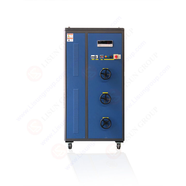
## 2.1 Multi-Module Pulse Generator Architecture
The LISUN EMS-ISO7637 system is engineered as a modular, integrated platform. Its core is a precision multi-module pulse generator capable of producing all standard pulses defined in ISO 7637-2:2021 and ISO 7637-3:2016. Each pulse module is independently controlled and calibrated to generate waveforms with strict adherence to standard parameters, including rise time, pulse width, and source impedance. For instance, the P5a and P5b pulse generators are designed with specific energy storage and switching networks to accurately replicate alternator field decay transients as per clause 5.5 of ISO 7637-2:2021. This modularity ensures future-proof testing as standards evolve.
## 2.2 Dual-Voltage System and DUT Integration
To accommodate the full spectrum of automotive applications, the system natively supports testing at 12V, 24V, and 36V DC power systems. It integrates essential peripheral equipment for a complete test setup:
* **Artificial Network (AN):** Provides a defined RF impedance between the DUT and the test generator, as required by the standards, and serves as a monitoring point.
* **Capacitive Coupling Clamp (CCC):** Used for coupling transient pulses (e.g., P3) onto non-supply lines per ISO 7637-3:2016, clause 5, without direct electrical connection.
* **Programmable DC Power Supply:** Provides stable, adjustable power to the DUT under test, simulating the vehicle's electrical system.
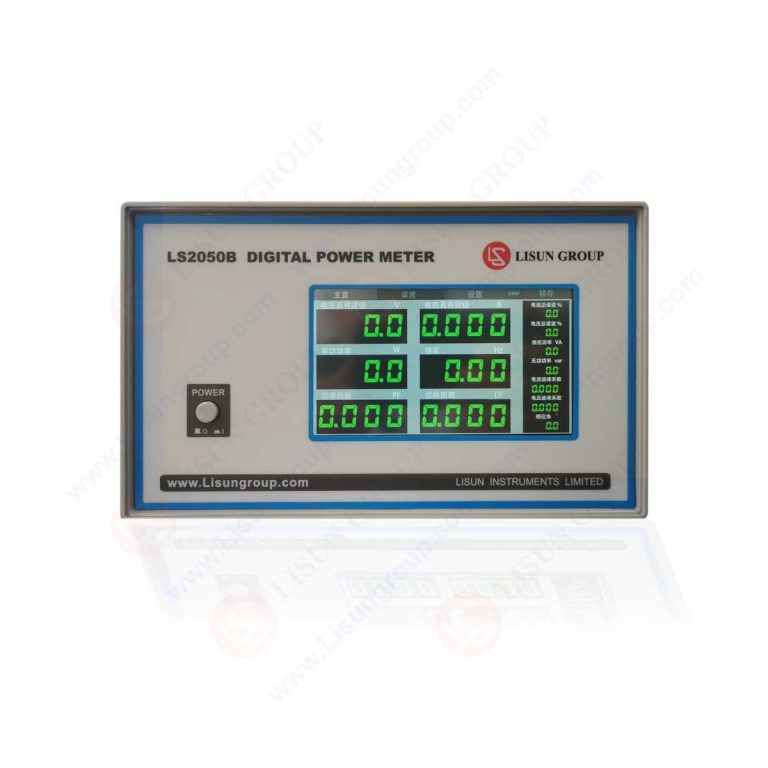
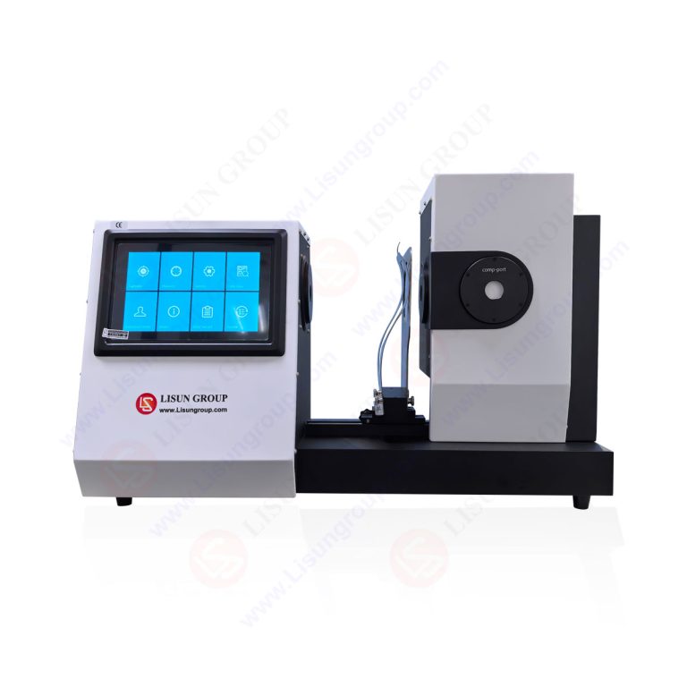
## 2.3 Automated Control and Reporting Software
A defining feature of the system is its dual-interface control: a local touchscreen HMI for manual operation and setup, and comprehensive PC software for automated sequence execution. The software allows engineers to pre-program complete test sequences—defining pulse type, level, repetition rate, and duration—which are then executed unattended. Crucially, all test parameters, pass/fail criteria (monitored via DUT status), and waveform data are automatically logged. This facilitates the generation of detailed, audit-ready test reports in formats like PDF or Excel, ensuring full traceability and compliance with quality management systems.
# 3. Technical Specifications and Comparative Performance
## 3.1 Key System Specifications
The EMS-ISO7637 system is characterized by high-performance specifications designed to meet and exceed standard requirements:
* **Pulse Coverage:** Full generation of P1, P2a, P2b, P3, P4, P5a, P5b pulses per ISO 7637-2 & -3.
* **Voltage Ranges:** P1 up to -200V; P2a up to +100V; P2b up to -100V; P3a/b up to ±150V; P4 up to +200V; P5a up to +168V; P5b up to +100V.
* **Source Impedance:** Precisely controlled per pulse type (e.g., 0.5Ω for P2a, 2Ω for P2b, 50Ω for P3).
* **Calibration Accuracy:** Better than ±5% for voltage and timing parameters, ensuring reliable and repeatable results.
* **Automation:** Fully programmable test sequences with automatic DUT monitoring and data recording.
## 3.2 Compliance Benchmarking Table
The following table compares the EMS-ISO7637 system's capabilities against the minimum requirements of key standards and typical implementation challenges.
| Feature / Parameter | ISO 7637-2:2021 / ISO 7637-3:2016 Requirement | EMS-ISO7637 System Specification | Typical Competitive Challenge |
| :--- | :--- | :--- | :--- |
| **Pulse Coverage** | P1, P2a, P2b, P3, P4, P5a, P5b | All pulses generated within one integrated system. | Often requires multiple separate generators or modules. |
| **Voltage System Support** | Test levels defined for 12V/24V systems. | Native support for 12V, 24V, and 36V systems. | May require external adaptation or separate systems for 24V/36V. |
| **Pulse 3 (Fast Transient) Coupling** | Capacitive coupling clamp (CCC) method. | Integrated CCC with calibrated coupling capacitance. | Use of non-standard or poorly characterized coupling networks. |
| **Test Automation & Reporting** | Standard defines procedure, not reporting format. | Fully automated sequences with integrated DUT monitoring and customizable report generation. | Manual operation and data collection, leading to potential human error and reporting delays. |
| **Calibration Traceability** | Requires periodic verification of pulse parameters. | High-accuracy calibration (<±5%) with documented traceability to national standards. | Marginal compliance with tolerance limits, reducing test margin and confidence. |
# 4. Application Scenarios in the Automotive Industry
## 4.1 Research, Development, and Design Verification
During the R&D phase, engineers use the system for design margin analysis and failure mode investigation. By subjecting prototypes to standardized and even beyond-standard pulse levels, weaknesses in power supply conditioning, filtering, or PCB layout can be identified and rectified early. The system's ability to quickly iterate through test parameters accelerates the design-for-EMC process, reducing costly late-stage redesigns. Automated reporting provides clear evidence of design evolution and compliance for internal reviews.
## 4.2 Production Line End-of-Line (EOL) Sampling
For quality control in mass production, the system can be configured for rapid, go/no-go testing on sampled units. A simplified test sequence, focusing on critical pulses like P1 (load dump) and P3 (fast transient), can be automated to verify that manufacturing processes have not introduced EMC vulnerabilities. The dual touchscreen/PC operation allows line technicians to initiate tests easily while maintaining full data logging for quality audits, aligning with OEM requirements like those in VW 80000.
## 4.3 Third-Party Laboratory Compliance Certification
Testing laboratories require equipment that delivers unambiguous, repeatable results for official certification reports. The EMS-ISO7637 system's calibration accuracy and adherence to standard waveforms (e.g., P5a's specific 40ms decay time per ISO 7637-2:2021, clause 5.5.2) are critical. Its automated reporting function directly feeds into the lab's documentation system, streamlining the generation of compliant test reports for standards such as GB/T 21437.2-2021, which is mandatory for the Chinese market.
# 5. Special Considerations for New Energy Vehicles (NEVs)
## 5.1 Testing High-Voltage Components
While ISO 7637 traditionally focuses on 12V/24V systems, its principles are directly applicable to the lower-voltage control networks within NEVs (e.g., 12V auxiliary system). Components like the Battery Management System (BMS), On-Board Charger (OBC) control unit, and DC-DC converter controllers must be immune to transients on these networks. The EMS-ISO7637 system is essential for validating these components. Furthermore, the transients themselves can originate from high-voltage contactor switching or charger interactions, making immunity testing even more critical.
## 5.2 Extended Test Requirements and System Adaptability
NEV-specific standards and OEM specifications often extend basic ISO 7637 requirements. They may mandate higher test levels, more pulse repetitions, or unique test sequences that simulate real-world NEV operating scenarios (e.g., charging while the vehicle is on). The programmable nature of the EMS-ISO7637 system allows it to adapt to these extended requirements. Test engineers can create custom pulse sequences or modify standard ones to meet the specific clauses of evolving NEV-focused standards, future-proofing the testing infrastructure.
# 6. Implementing a Transient Immunity Test Plan
## 6.1 Defining the Test Setup and DUT Configuration
A compliant test begins with a rigorous setup as defined in ISO 7637-2:2021, clause 6. The DUT is powered via the Artificial Network (AN), and all other lines are configured with appropriate cable harnesses and, if necessary, the Capacitive Coupling Clamp. The DUT's functional performance must be monitored throughout the test, often requiring custom monitoring software or hardware to detect resets or latent faults. The system's software allows for the integration of these monitoring signals to automatically determine a pass/fail status based on predefined criteria.
## 6.2 Executing the Test Sequence and Data Analysis
The test sequence is executed according to the applicable standard and OEM specification. For example, GM 3172 may specify a particular order and duration for applying P2b pulses. The automated system applies each pulse at the specified level, repetition rate, and duration while continuously monitoring the DUT. All applied waveforms (actual voltage/current at the AN) are recorded. Post-test, engineers can analyze this data to verify that the applied pulses met standard tolerances and correlate any DUT malfunctions with specific pulse events, providing invaluable diagnostic information.
# 7. The Critical Role of Automated Reporting
## 7.1 Ensuring Traceability and Audit Compliance
In regulated industries, test traceability is non-negotiable. Automated reporting eliminates manual transcription errors and ensures every test parameter—pulse shape, exact voltage level, timing, DUT response—is permanently recorded alongside timestamps and operator information. This creates an immutable audit trail that satisfies the requirements of quality standards (e.g., IATF 16949) and certification bodies. It provides unequivocal proof that testing was performed in full compliance with the referenced standard clauses.
## 7.2 Enhancing Laboratory Efficiency and Data Integrity
Manual report generation is a significant time sink. The automated reporting function of the EMS-ISO7637 system transforms raw test data into a structured, professional report in minutes. This dramatically increases laboratory throughput and allows engineers to focus on data analysis and problem-solving rather than administrative tasks. Furthermore, by storing data in digital formats, it enables long-term trend analysis, comparison between product generations, and easy data retrieval for customer inquiries or technical reviews.
# Conclusion
The relentless electrification and connectivity of vehicles have made rigorous transient immunity testing a cornerstone of automotive EMC strategy. The **EMS-ISO7637 Automotive Electronics Transient Immunity EMC Testing System** represents a sophisticated, integrated solution that addresses the full spectrum of this challenge, from standard compliance to adaptable application-specific testing. Its technical merits—precise pulse generation, multi-voltage support, and crucially, end-to-end automation with robust reporting—deliver tangible value across the product lifecycle. For R&D teams, it accelerates robust design; for production QC, it ensures consistent quality; and for certification labs, it guarantees reliable, auditable results. As the industry advances towards software-defined and all-electric vehicles, investing in such a comprehensive and automated testing system is not merely a compliance exercise but a strategic imperative for ensuring the safety, reliability, and market success of automotive electronic components in an increasingly demanding electromagnetic world.
# FAQ (Frequently Asked Questions)
**Q1: How does the EMS-ISO7637 system handle testing for both 12V and 24V vehicle systems, and is it suitable for the 48V mild-hybrid systems?**
A: The system features native, integrated power sourcing and pulse generation networks specifically designed for 12V, 24V, and 36V DC systems. Switching between these voltages is typically managed within the control software, which automatically adjusts the internal configurations and test level scaling to maintain standard compliance for pulses like P1, P2a/b, and P4. For 48V systems, while not a traditional ISO 7637 voltage, the 36V-capable modules of the EMS-ISO7637 often provide sufficient headroom to test 48V components at scaled levels. However, testing to specific 48V OEM specifications (e.g., LV148) may require consultation to ensure the generator's output range and source impedance can accurately replicate the required 48V-specific transient waveforms.
**Q2: What is the difference between testing per ISO 7637-2 and ISO 16750-2, and can the EMS-ISO7637 system cover both?**
A: ISO 7637-2 is a dedicated standard specifying the exact waveforms (P1-P5b), test methods, and setups for immunity to electrical transients on supply lines. ISO 16750-2:2023, "Road vehicles — Environmental conditions and testing for electrical and electronic equipment — Part 2: Electrical loads," is a broader standard covering the complete electrical environment, including DC voltage variations, slow transients, and superimposed AC ripple. While it references ISO 7637-2 for transient immunity, it also includes other tests like load dump (similar to P4 but with different parameters). The EMS-ISO7637 system is specifically designed for the pulses in ISO 7637-2/3. To fully cover ISO 16750-2, it would be used in conjunction with other equipment, such as a programmable DC power supply for DC variation tests, with the system's automation software potentially coordinating the overall test sequence.
**Q3: For testing non-supply lines (signal/communication lines) as per ISO 7637-3, what additional equipment is needed with the pulse generator?**
A: Testing to ISO 7637-3:2016 requires a specific coupling network to inject transients without galvanic connection. The primary tool is a **Capacitive Coupling Clamp (CCC)**, as specified in clause 5 of the standard. The EMS-ISO7637 system typically includes or is compatible with a calibrated CCC. The test setup involves placing the bundled DUT signal/communication cable harness through the CCC. The transient pulse (e.g., P3) is then applied to the clamp, which capacitively couples the energy onto the lines inside the bundle. The generator must be capable of producing the required fast transient pulses (P3a/P3b) with the correct source impedance (50Ω) to drive the CCC effectively, which is a core capability of the integrated system.
**Q4: How does the automated reporting feature handle a DUT failure during a long, unattended test sequence?**
A: The automated test software is designed for robust failure management. During sequence execution, it continuously monitors the DUT's status input (e.g., a "heartbeat" signal or functional performance monitor). If a failure is detected—such as the DUT resetting or a monitored signal going out of specification—the software can be configured to take several actions: 1) Immediately halt the test sequence, 2) Log the exact time, test step, and pulse parameters at the moment of failure, 3) Save the oscilloscope waveform of the failing pulse, and 4) Flag the test as "FAILED" in the report summary. This ensures that failure events are captured with precise contextual data, greatly aiding engineers in subsequent diagnostic and root-cause analysis activities.