


Abstract
Ensuring the electromagnetic compatibility (EMC) of automotive electronic components against transient disturbances is a critical pillar of vehicle safety and reliability. This article provides a comprehensive technical analysis of the EMS-ISO7637 Automotive Electronics Transient Immunity EMC Testing System for NEV Components, a sophisticated platform designed to validate the robustness of electronic control units (ECUs), power converters, and battery management systems (BMS) against the harsh electrical transients present in vehicle power networks. We will explore the system’s architecture, its precise alignment with international and national standards, and its application across the automotive product lifecycle. The discussion will detail how the LISUN EMS-ISO7637 system, through its multi-pulse generation capabilities and automated test sequences, addresses the stringent requirements of modern passenger cars, commercial vehicles, and new energy vehicles (NEVs), ensuring compliance and enhancing product quality from R&D to mass production.

1.1 The Electrical Environment of a Vehicle
The automotive electrical system is a hostile electromagnetic environment. Beyond the nominal 12V, 24V, or higher voltage levels, components are subjected to a complex array of transient disturbances. These originate from inductive load switching (e.g., relays, motors), load dump events when alternators are disconnected, and coupling from adjacent high-current cables. For New Energy Vehicles (NEVs), the high-voltage traction system (typically 400V or 800V DC) and high-power switching in On-Board Chargers (OBCs) and DC-DC converters introduce additional, severe transient threats. These fast-rising, high-energy pulses can cause microcontroller resets, memory corruption, or permanent damage to sensitive semiconductors, directly impacting vehicle functionality and safety.
1.2 Standards as the Compliance Framework
To mitigate these risks, a robust framework of international and OEM-specific standards defines test requirements. The ISO 7637 series is the global benchmark, with ISO 7637-2:2021 specifying test pulses for electrical transient conduction along supply lines, and ISO 7637-3:2016 covering transient transmission via capacitive and inductive coupling. National equivalents like GB/T 21437.2-2021 and GB/T 21437.3-2021 are mandatory in China. Furthermore, OEMs enforce even stricter internal standards, such as Volkswagen’s VW 80000 or General Motors’ GM 3172, which often specify more severe test levels or additional pulse shapes. Compliance with this multi-layered standard hierarchy is non-negotiable for component suppliers.
2.1 Core System Components and Functionality
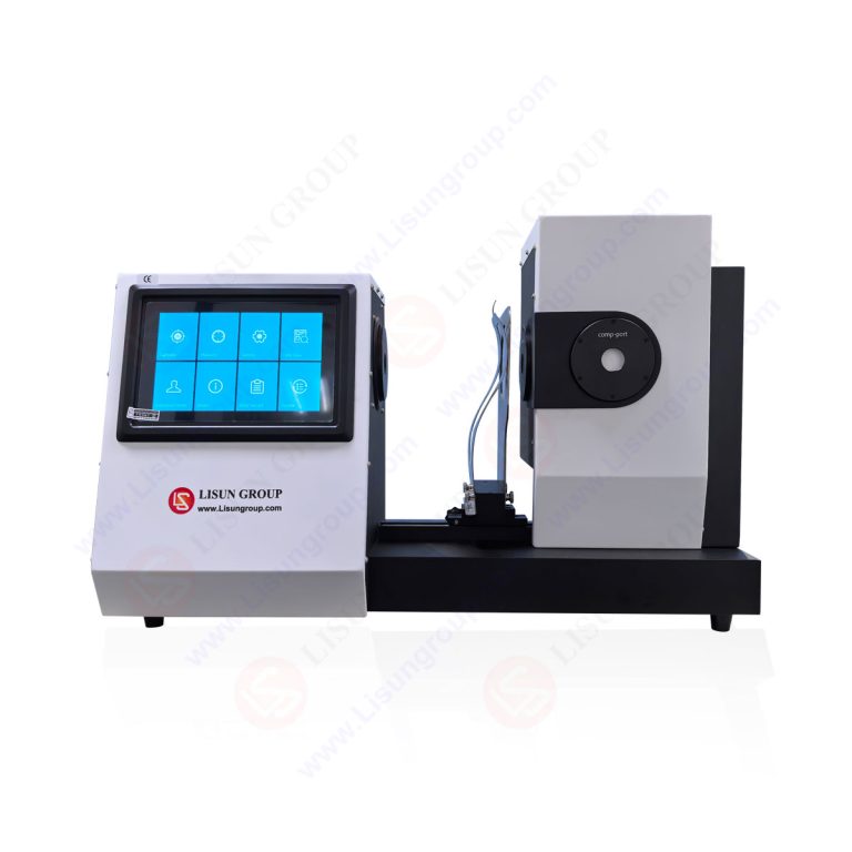
The LISUN EMS-ISO7637 system is an integrated solution engineered to replicate the transient disturbances defined by automotive standards. Its architecture centers on a high-precision, multi-module pulse generator capable of producing the full suite of required test pulses: P1, P2a, P2b, P3, P4, P5a, and P5b. The system interfaces with the Device Under Test (DUT) through essential ancillary equipment, including a 5µH Artificial Network (AN) to provide a defined source impedance as per ISO 7637-2:2021 Clause 5.2, and a Capacitive Coupling Clamp (CCC) for non-contact coupling tests per ISO 7637-3:2016. A dual-channel monitoring system measures both the injected pulse and the DUT’s supply voltage, ensuring test accuracy.
2.2 Operational Flexibility and User Interface
Designed for efficiency in both laboratory and production settings, the system offers dual operational modes. Engineers can execute tests directly via a large, intuitive touchscreen interface on the mainframe for quick setup and debugging. For complex, automated test sequences, a comprehensive PC-based software provides full control, allowing for the programming of multi-pulse test plans, real-time data logging, and the automatic generation of detailed test reports in formats like PDF or Excel. This flexibility streamlines workflows from initial R&D verification to high-throughput end-of-line quality audits.
3.1 Comprehensive Pulse Coverage and Voltage System Support
The system’s pulse generator is characterized by its wide parametric range, ensuring coverage of all standard test levels. It supports the high-voltage, high-energy pulses like P5a (load dump simulation) and the fast, repetitive pulses like P3a/P3b (switching of inductive loads). Critically, it is designed for multi-voltage platform testing, seamlessly supporting 12V, 24V, and 36V vehicle electrical systems, which is essential for testing components for commercial vehicles and specialized NEV applications beyond the common 12V architecture.
3.2 Calibration and Measurement Accuracy
Measurement integrity is paramount. The system incorporates high-bandwidth, high-voltage differential probes and precision measurement circuits to capture transient waveforms with fidelity. Key parameters such as pulse rise time, duration, and amplitude are verified against reference calibrators traceable to national standards. This ensures that the test severity applied to the DUT is exactly as specified in the standards, a fundamental requirement for generating credible and recognized test reports for certification bodies.
Table 1: LISUN EMS-ISO7637 System Pulse Specification vs. ISO 7637-2:2021 Requirements
| Test Pulse | Typical Source | Key Parameter (ISO 7637-2) | LISUN EMS-ISO7637 Capability | Compliance Note |
|---|---|---|---|---|
| P1 | Disconnection of inductive loads | -Us to +Us, tr: 1ms | Voltage Range: ±200V, tr: Adjustable 0.5ms – 2ms | Meets and exceeds timing flexibility |
| P2a/b | Interruption of current to parallel loads | +Us to -Us, t1: 0.05s/0.5s | Voltage Range: ±200V, t1: Precisely programmable | Fully covers standard timing requirements |
| P3a/b | Switching of inductive loads | ±Vs, tr/ti: ns-µs range | Fast edge: < 5ns, High Repetition | Exceeds requirements for fast transients |
| P4 | Starting of diesel engines | +Us, duration: 0.1-4s | High-current source, programmable duration | Simulates long-duration cranking surges |
| P5a/b | Load dump (alternator disconnect) | +Us to +Vmax, t6/t7: 40-400ms | High Energy: Up to 500W, t6/t7 programmable | Meets high-energy dissipation requirements |
4.1 Research, Development, and Design Verification
In the R&D phase, the EMS-ISO7637 system is used for design margin analysis and failure mode investigation. Engineers can apply standardized pulses or create custom waveforms to stress prototypes, identify weak points in power supply conditioning circuits (e.g., TVS diodes, LC filters), and optimize designs before formal compliance testing. This iterative process, referencing standards like ISO 16750-2:2023 for general electrical environmental conditions, reduces costly redesigns and accelerates time-to-market.
4.2 Type Approval and Third-Party Laboratory Certification
For final product validation, the system enables precise execution of the complete test matrix mandated by standards. Test laboratories use it to generate official compliance reports for components such as Engine ECUs, Body Control Modules (BCMs), and telematics units. The system’s ability to document every test parameter and result with audit trails is critical for meeting the rigorous quality management requirements of certification bodies and OEMs reviewing data per VW 80000 or GM 3172 protocols.
4.3 Mass Production Inspection and Quality Control
Beyond R&D, the system’s automation features are leveraged in production environments. High-volume manufacturers can implement sampling-based or 100% end-of-line tests using pre-programmed “pass/fail” sequences. This ensures that manufacturing process variations do not compromise the transient immunity of components like window lift motors, sensors, or infotainment systems, providing a final quality gate before shipment to vehicle assembly plants.
5.1 High-Voltage Component Challenges
NEV components operate in a uniquely demanding EMC environment. The EMS-ISO7637 Automotive Electronics Transient Immunity EMC Testing System for NEV Components is specifically configured to address these. While the high-voltage battery and traction inverter have their own EMC standards, the low-voltage (12V/24V) control networks that manage them are still vulnerable. Transients coupled from the high-voltage system can propagate into these control circuits, threatening critical functions.
5.2 Testing Key NEV Subsystems
The system is essential for validating the robustness of core NEV subsystems:
- Battery Management Systems (BMS): The BMS must remain fully operational during all transients to prevent unsafe battery states. Testing verifies immunity for its communication and sensor lines.
- On-Board Chargers (OBC) & DC-DC Converters: These contain high-power switching electronics that are both sources of, and susceptible to, transients. Testing ensures their control logic and low-voltage interfaces are immune to disturbances generated by their own operation or external events, as outlined in extended application guides referencing ISO 7637 and GB/T 21437 series.
- Vehicle Control Units (VCUs) and Inverter Gate Drivers: As the central nervous system of the NEV, the VCU’s immunity is paramount. Testing protects against faults that could lead to unintended torque delivery or system shutdowns.
6.1 Synergy with Radiated Immunity Testing
Transient immunity is one facet of a complete EMC assessment. The EMS-ISO7637 system often operates in conjunction with radiated immunity test systems (e.g., according to ISO 11452-2). A component must withstand both conducted transients on its wiring harness and electromagnetic fields penetrating its enclosure. A holistic test plan will sequence these tests to uncover cumulative stress effects.
6.2 Automated Test Sequencing and Data Management
For maximum efficiency, the system’s PC software can be integrated into a laboratory-wide test executive. This allows for the creation of unified test sequences that might, for example, apply a specific transient pulse (per ISO 7637-2) immediately after exposing the DUT to a radiated RF field. All data—waveforms, DUT performance monitoring (via CAN/LIN), and pass/fail status—is consolidated into a single, searchable database, streamlining report generation and audit processes for complex projects.
7.1 Defining the Test Plan and DUT Configuration
Success begins with a meticulously defined test plan based on the relevant product standard and OEM specifications. This includes selecting the correct test pulses, severity levels (I-IV), and DUT operating modes (e.g., sleep, active, full load). The physical test setup is equally crucial: wiring harness length and routing must be representative, the 5µH AN must be correctly placed, and the DUT must be powered via a clean, stabilized supply as specified in the standard’s test setup clauses.
7.2 Monitoring for Functional Status and Performance Criteria
Applying the pulse is only half the test. Continuously monitoring the DUT’s functional status is essential. This involves defining clear Performance Criteria (e.g., Class A: normal performance; Class B: temporary degradation; Class C: reset required; Class D: permanent damage) and implementing monitoring methods. These can range from simple LED observation to automated software scripts monitoring CAN bus messages for error frames or validating specific sensor outputs, ensuring an objective and repeatable assessment of immunity.
The EMS-ISO7637 Automotive Electronics Transient Immunity EMC Testing System represents a critical investment in product quality and market access for any automotive electronics supplier. By providing a precise, reliable, and standards-compliant means of simulating the harsh transient environment of a vehicle, it enables engineers to uncover design vulnerabilities early, verify compliance with a complex web of international and OEM-specific standards, and implement rigorous quality controls in production. For the rapidly evolving New Energy Vehicle sector, its role is even more pronounced, safeguarding the intricate electronic systems that control high-voltage energy and propulsion. Ultimately, deploying such a system is not merely about passing a test; it is a fundamental engineering practice that directly contributes to the functional safety, reliability, and longevity of modern vehicles, building trust in an increasingly electronic and software-defined automotive landscape.
Q1: How does the EMS-ISO7637 system handle testing for both 12V and 24V vehicle systems, and is it suitable for 48V mild-hybrid systems?
A: The LISUN EMS-ISO7637 system is designed with multi-voltage capability, featuring internal switching and programmable power supplies that allow it to be configured for standard 12V and 24V nominal systems seamlessly. For testing to ISO 7637-2:2021, the test pulse amplitudes (e.g., for P1, P2a) are defined as multiples of the DUT’s nominal supply voltage (Us), which the system automatically calculates. Regarding 48V systems, while the current ISO 7637-2 standard formally covers up to 36V, the system’s hardware (e.g., its pulse generator’s voltage and current headroom) is often capable of being applied to 48V architectures by using the 36V setting as a base and scaling test plans accordingly, though this should be validated against specific OEM specifications like VW 80000 which may have dedicated 48V test clauses.
Q2: What is the purpose of the 5µH Artificial Network (AN), and is it always required during testing?
A: The 5µH Artificial Network is a fundamental component specified in ISO 7637-2:2021, Clause 5.2. Its primary purpose is to provide a defined, repeatable source impedance (5µH in series with 0-50mΩ) between the pulse generator and the Device Under Test (DUT). This simulates the realistic inductance of a vehicle’s wiring harness and ensures that the transient pulse delivered to the DUT is consistent and reproducible across different laboratories. It is mandatory for all “coupling/decoupling” tests where pulses are directly injected into the supply lines. It is not used for capacitive coupling tests (per ISO 7637-3:2016), which instead utilize a Capacitive Coupling Clamp (CCC).
Q3: Can the system generate and test the “P8” pulse mentioned in some Chinese standards, and how does GB/T 21437 relate to ISO 7637?
A: Yes, advanced configurations of the LISUN EMS-ISO7637 system can generate the P8 pulse (simulating a sudden battery disconnect during regenerative braking) and other pulses defined in the Chinese national standards GB/T 21437.2-2021 and GB/T 21437.3-2021. These standards are largely technically aligned with ISO 7637-2:2011 and ISO 7637-3:2016, respectively, but include important national differences and additions, such as the P8 pulse. For the Chinese market, compliance with GB/T 21437 is often mandatory for vehicle type approval. The system’s software typically includes pre-configured test templates for both ISO and GB/T series, allowing engineers to execute the correct test plan for their target market.
Q4: How does automated test software improve the efficiency and accuracy of compliance testing compared to manual operation?
A: The PC-based automation software transforms the testing process from a manual, error-prone operation into a streamlined, auditable procedure. It allows engineers to program complete test sequences—including all pulses, levels, durations, and necessary DUT mode changes—which are then executed unattended. This eliminates operator variability in timing and setup. The software automatically captures and time-stamps all pulse waveforms, monitors DUT status, and applies pre-defined performance criteria to generate a pass/fail report. This not only saves significant time, especially for multi-pulse test plans, but also creates a complete digital audit trail essential for certification audits and internal quality management systems.