


Ensuring Product Durability Through Thermal Shock Testing
Introduction to Thermal Stress and Product Reliability
In the competitive landscape of modern manufacturing, product reliability is not merely an aspiration but a fundamental requirement. Components and assemblies across a vast array of industries are subjected to environmental extremes that can precipitate catastrophic failure. Among these stressors, rapid temperature fluctuation represents a particularly severe challenge. The differential expansion and contraction of dissimilar materials induce mechanical stresses that can fracture solder joints, delaminate substrates, crack encapsulations, and compromise hermetic seals. Thermal shock testing, therefore, serves as a critical accelerated life test, simulating years of environmental exposure within a controlled laboratory timeframe. This rigorous validation process is indispensable for identifying latent design flaws, qualifying manufacturing processes, and ultimately ensuring that products meet their intended service life in real-world conditions, from the controlled environment of a data center to the punishing thermal cycles of an automotive engine bay.
The Fundamental Physics of Thermal Shock Failure Mechanisms
Thermal shock induces failure through the generation of thermomechanical stress. When a material or a multi-material assembly experiences a rapid temperature change, its constituent parts attempt to expand or contract at rates dictated by their respective coefficients of thermal expansion (CTE). A pronounced CTE mismatch, such as that between a silicon semiconductor die (CTE ~2.6 ppm/°C) and an FR-4 printed circuit board (CTE ~14-18 ppm/°C in the X-Y plane), creates shear forces at the interface. These forces are concentrated at the weakest points: solder interconnects, wire bonds, adhesive layers, and glass-to-metal seals.
The failure modes are multifaceted. In electronics, cyclic stress leads to solder joint fatigue, manifested as crack initiation and propagation, ultimately resulting in electrical opens. For encapsulated components, such as those found in automotive control units or industrial sensors, repeated stress can cause the epoxy molding compound to separate from the lead frame or the chip surface, allowing moisture ingress and leading to corrosion. In lighting fixtures, particularly high-brightness LEDs, thermal shock can degrade the phosphor layer, alter chromaticity, and weaken the bond between the LED package and the heat sink, drastically reducing luminous efficacy and lifespan. Understanding these physics underscores the necessity of a test that faithfully replicates the rate and magnitude of real-world temperature transitions.
Methodologies and Standards Governing Thermal Shock Testing
Thermal shock testing is governed by a suite of international standards that define test parameters, including temperature extremes, dwell times, transfer time, and number of cycles. These standards provide a common language for specification and compliance across industries.
- IEC 60068-2-14 (Environmental testing – Part 2-14: Tests – Test N: Change of temperature): A foundational standard detailing various test methods, including rapid change of temperature (Test Na), which is synonymous with two-zone thermal shock.
- MIL-STD-202G, Method 107G (Thermal Shock): Widely referenced in military and aerospace applications, this method specifies stringent requirements for components destined for extreme environments.
- JESD22-A104 (Temperature Cycling): While often associated with slower temperature cycles, it provides the framework for defining thermal shock conditions for semiconductor devices.
- Automotive Standards (e.g., ISO 16750-4, LV 124): These standards define specific test profiles for automotive electronics, often requiring extreme temperature ranges (e.g., -40°C to +125°C) to simulate under-hood and in-cabin conditions.
The two predominant test methodologies are the Two-Zone (Transfer) Method and the Single-Zone (Liquid-to-Liquid) Method. The two-zone method, utilizing separate high-temperature and low-temperature chambers, is the most common for assembled electronics, as it avoids the contaminating and conductive effects of fluids. The transfer of the test specimen between zones must be rapid, typically under 10 seconds, to prevent temperature stabilization during transit and ensure the intended shock is delivered.
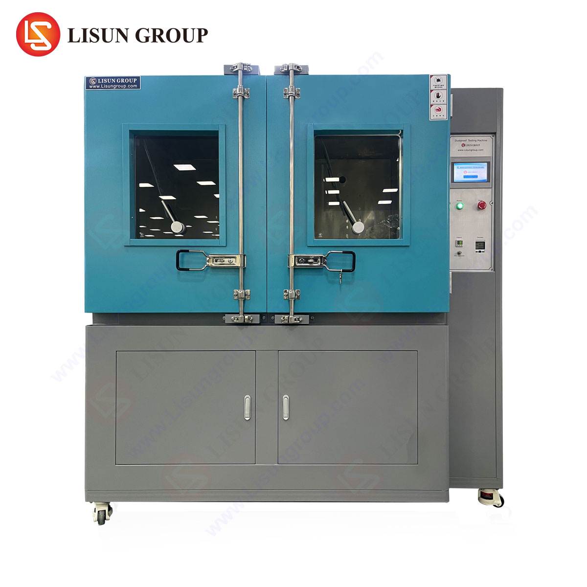
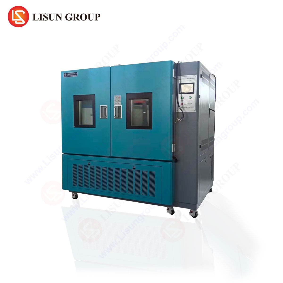
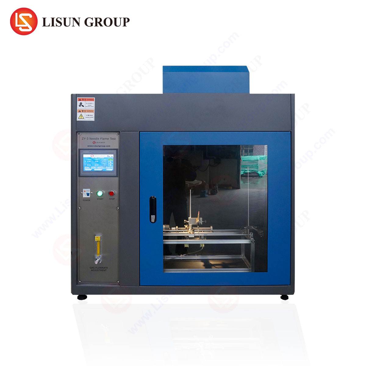
The HLST-500D Thermal Shock Test Chamber: Architecture and Operational Principle
The LISUN HLST-500D Thermal Shock Test Chamber embodies the two-zone transfer methodology in a self-contained, vertically oriented system. Its design is optimized to deliver precise, repeatable, and severe thermal shock conditions for component and sub-assembly qualification.
Core Specifications:
- Test Volume: 500 Liters (interior dimensions customizable)
- Temperature Range: High Temperature Chamber: +60°C to +200°C; Low Temperature Chamber: -10°C to -65°C (extendable to -80°C)
- Recovery Time: ≤5 minutes (from +150°C to -55°C or vice-versa, under full load)
- Transfer Time: <10 seconds (mechanical lift system)
- Temperature Fluctuation: ≤±0.5°C
- Temperature Uniformity: ≤±2.0°C
- Control System: Programmable touch-screen controller with data logging and USB interface for profile storage and results export.
Operational Principle: The test specimen is loaded into a basket within the transfer mechanism. The test commences with a dwell period in either the high- or low-temperature zone. Upon completion of the dwell, the basket is rapidly elevated or lowered into the opposing zone. This mechanical transfer occurs in seconds, subjecting the product to an instantaneous temperature delta. The system’s high-capacity refrigeration and heating systems ensure the chambers rapidly recover to setpoint after the thermal mass of the basket and product is introduced, maintaining the integrity of the test profile over hundreds or thousands of cycles.
Industry-Specific Applications and Validation Use Cases
The HLST-500D is deployed across industries to validate product robustness. Below are illustrative use cases:
- Automotive Electronics: An engine control module (ECM) is subjected to 1,000 cycles between -40°C and +125°C. The test reveals micro-cracking in quad flat no-lead (QFN) package solder joints, leading to a redesign of the PCB pad geometry and stencil aperture to improve solder volume and fatigue life.
- Telecommunications Equipment: A 5G millimeter-wave antenna module undergoes thermal shock from -55°C to +85°C. The test identifies delamination between a ceramic substrate and a copper heat spreader, prompting a change in the solder attach material and process to ensure signal integrity in outdoor deployments.
- Medical Devices: A portable insulin pump’s internal electronics are cycled between +5°C (simulating refrigeration) and +40°C (body-adjacent temperature). The test validates that the epoxy potting compound maintains adhesion to the battery terminals and microcontrollers, preventing moisture ingress that could cause a critical failure.
- Aerospace and Aviation Components: Avionics connectors with hermetic glass seals are tested from -65°C to +175°C. Helium leak testing before and after thermal shock confirms the seal’s integrity, ensuring performance at high altitude.
- Lighting Fixtures: A high-bay LED luminaire for industrial use is cycled between -30°C and +85°C. Post-test analysis shows a shift in the correlated color temperature (CCT) beyond acceptable limits, traced to phosphor degradation. This leads to the qualification of a more thermally stable phosphor formulation.
- Electrical Components: Molded case circuit breakers are shocked to verify that the thermal bimetal trip mechanism calibrates correctly and that the housing does not become brittle or warp, which could affect arc chute alignment and safety.
Analytical Advantages of Precision Thermal Shock Equipment
The value of a chamber like the HLST-500D extends beyond mere specification compliance. Its precision offers distinct analytical advantages:
- Accelerated Failure Reproduction: By applying stresses more severe than typical field conditions, it compresses failure timelines, allowing engineers to identify and rectify design weaknesses during the development phase, far before mass production.
- Process Qualification: It serves as a critical tool for qualifying manufacturing processes, such as reflow soldering profiles, conformal coating application, and potting. A batch of samples that survives a prescribed thermal shock regimen provides high confidence in process control.
- Comparative Analysis: It enables objective comparison between different material choices (e.g., two types of underfill), component suppliers, or assembly techniques by subjecting them to identical, repeatable stress.
- Correlation to Field Data: When failure modes induced in the chamber match those observed in field returns, a powerful correlation is established. This allows for the refinement of test profiles to better predict real-world reliability, creating a feedback loop that continuously improves product design.
Table 1: Example Thermal Shock Test Profile for Automotive Under-Hood Electronics
| Parameter | Value | Standard Reference |
| :— | :— | :— |
| High Temperature | +125 °C | ISO 16750-4 |
| Low Temperature | -40 °C | ISO 16750-4 |
| Dwell Time | 30 minutes | (Ensures thermal stabilization) |
| Transfer Time | < 10 seconds | HLST-500D Capability |
| Number of Cycles | 500 | Customer-specific requirement |
| Condition Monitoring | In-situ resistance monitoring of daisy-chained test boards | IPC-9701 |
Integrating Thermal Shock into a Comprehensive Reliability Strategy
Thermal shock testing is not a standalone activity but a vital component of a holistic reliability engineering program. It should be strategically sequenced with other tests. For instance, thermal shock is often performed after temperature cycling (which induces fatigue through slower, less severe cycles) and before or in conjunction with vibration or mechanical shock testing. The combination of thermal and mechanical stress, known as combined environment testing, is the most accurate method for simulating real-world conditions, such as those experienced by a satellite component during launch and orbital insertion, or by automotive electronics on a rough, cold road.
Furthermore, data from thermal shock tests feed into reliability prediction models. The number of cycles-to-failure for a given temperature delta can be analyzed using models like the Coffin-Manson relationship, helping to extrapolate field failure rates and inform warranty analyses.
Conclusion
In an era where product failure carries significant financial, reputational, and sometimes safety-related consequences, the role of rigorous environmental validation cannot be overstated. Thermal shock testing, as facilitated by precision instrumentation like the LISUN HLST-500D Thermal Shock Test Chamber, provides an uncompromising assessment of a product’s ability to withstand the rigors of thermal transients. By deliberately inducing and analyzing failure in the laboratory, engineers can design out weaknesses, qualify robust manufacturing processes, and deliver products that achieve and exceed their reliability targets. This proactive approach to durability is not merely a test procedure; it is a fundamental pillar of quality engineering and a critical investment in product integrity and brand trust.
Frequently Asked Questions (FAQ)
Q1: What is the critical difference between temperature cycling and thermal shock testing?
A1: The primary distinction lies in the rate of temperature change. Temperature cycling involves relatively gradual ramps (e.g., 5°C to 15°C per minute) and is used to simulate slower, diurnal cycles, inducing fatigue. Thermal shock features an extremely rapid transition (achieving the temperature delta in seconds or minutes via chamber transfer), focusing on the mechanical stress from CTE mismatch during sudden environmental shifts, such as a device being powered on in a cold environment.
Q2: For the HLST-500D, what factors influence the chamber’s recovery time, and why is it important?
A2: Recovery time is influenced by the thermal mass (weight and specific heat) of the test load, the setpoint temperature delta, and the power of the chamber’s refrigeration and heating systems. A fast recovery time (<5 minutes for the HLST-500D under load) is crucial because it ensures the test specimens experience the full target temperature extreme for the majority of the dwell period, maintaining the severity and repeatability of the test profile.
Q3: Can the HLST-500D accommodate in-situ electrical testing during the thermal shock cycles?
A3: Yes, this is a critical capability. The chamber is typically equipped with ports for electrical feedthroughs. This allows test specimens to be connected to external monitoring equipment for continuous or intermittent measurements of resistance, continuity, capacitance, or functional performance during the test. This real-time monitoring can pinpoint the exact cycle at which a failure occurs, providing invaluable diagnostic data.
Q4: How do I determine the appropriate temperature extremes and number of cycles for my product?
A4: The test conditions should be derived from the product’s operational requirements and relevant industry standards. Start by identifying the maximum and minimum storage and operating temperatures specified in the product requirements document. Then, consult applicable standards (e.g., IEC, MIL, automotive OEM specifications) which often prescribe standardized test conditions. The number of cycles is typically a compromise between statistical confidence (more cycles are better) and development time/cost, often ranging from 50 to 1,000+ cycles based on the intended product life and criticality.
Q5: What are common post-test inspection techniques for components subjected to thermal shock?
A5: A combination of inspections is recommended: Electrical Testing to verify functionality and parametric performance; Visual Inspection under magnification for cracks, delamination, or discoloration; Scanning Acoustic Microscopy (CSAM) to detect internal delaminations or voids in encapsulated components; Cross-Sectioning for microscopic analysis of solder joint integrity, intermetallic compound formation, and crack propagation; and Dye-and-Pry Tests to expose the extent of cracking in solder joints.