


Ensuring Product Durability Through Thermal Shock Testing
Introduction to Thermal Stress Failure Mechanisms
In the rigorous landscape of modern manufacturing, product reliability is not merely an aspiration but a fundamental requirement. Components and assemblies across a diverse spectrum of industries are routinely subjected to environmental extremes that can precipitate catastrophic failure. Among these, rapid temperature transitions—thermal shock—represent a particularly insidious threat. Unlike gradual thermal cycling, thermal shock induces severe, transient mechanical stresses within materials and at the interfaces of dissimilar materials. These stresses arise from differential coefficients of thermal expansion (CTE), leading to phenomena such as delamination, solder joint fracture, ceramic substrate cracking, and hermetic seal failure. Consequently, the ability to simulate and evaluate a product’s resilience to such conditions is paramount. Thermal shock testing, therefore, serves as a critical validation tool, separating robust designs from those susceptible to premature field failure.
The Thermodynamic Principles Underpinning Accelerated Life Testing
Thermal shock testing operates on well-established principles of accelerated life testing (ALT). By exposing a test specimen to conditions far more severe than those encountered in typical service, the test compresses the failure timeline, revealing latent design or process flaws within a practical laboratory duration. The core mechanism is the rapid induction of thermal stress. When a component is transferred from a high-temperature zone to a low-temperature zone, or vice versa, its constituent materials contract or expand at rates dictated by their individual CTEs. If these materials are bonded or in mechanical contact—such as a silicon die attached to a copper lead frame with epoxy, or a surface-mount device (SMD) soldered to a printed circuit board (PCB)—the mismatch generates shear and tensile forces.
The severity of the stress is governed by the fundamental equation for thermal strain: ε = α ΔT, where ε is the induced strain, α is the coefficient of thermal expansion, and ΔT is the temperature change. The resulting stress, σ, is a function of this strain and the material’s modulus of elasticity, E, as described by σ = E α * ΔT (for constrained conditions). A thermal shock test chamber dramatically increases the ΔT and the rate of temperature change (dT/dt), thereby magnifying σ to levels that will quickly propagate microcracks, weaken bonds, and ultimately cause functional failure. This controlled application of extreme thermodynamic forcing functions allows engineers to identify the weakest links in a product’s construction.
Architectural Overview of a Two-Zone Thermal Shock Chamber
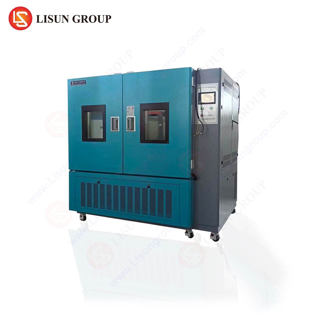
To execute these tests with precision and repeatability, specialized equipment is required. The two-zone (or two-basket) thermal shock test chamber is the industry-standard apparatus. Its design features two independently controlled climatic chambers: one for high temperature and one for low temperature. A mechanically driven transfer system, often a basket or elevator, shuttles the test specimens between these two zones with minimal transition time, typically under 10 seconds. This rapid transfer is crucial, as it prevents temperature stabilization during the move, ensuring the full thermal shock is delivered to the product.
The high-temperature chamber utilizes electric heating elements and a forced air circulation system to achieve and maintain uniformity. The low-temperature chamber employs a mechanical refrigeration system, commonly using cascade compressors with refrigerants like R404A or R23 to reach ultralow temperatures. Advanced units integrate sophisticated programmable logic controllers (PLCs) and touch-screen human-machine interfaces (HMIs) to manage complex test profiles, monitor conditions in real-time, and log data for compliance and analysis. The integrity of the test hinges on the chamber’s ability to maintain strict temperature stability in each zone and to execute transfers with unwavering speed and reliability.
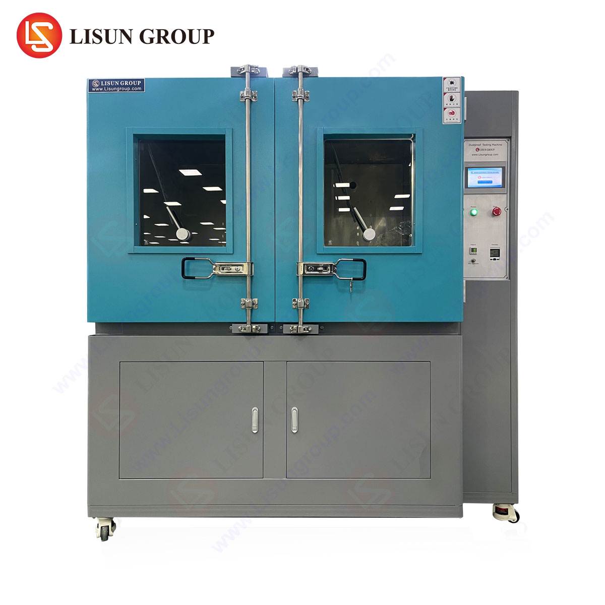
The HLST-500D Thermal Shock Test Chamber: A Technical Examination
A representative example of this specialized equipment is the LISUN HLST-500D Thermal Shock Test Chamber. This model is engineered to deliver rigorous thermal shock conditioning for components and assemblies across the aforementioned industries. Its design specifications and operational capabilities make it a pertinent tool for reliability validation.
The HLST-500D features a classic two-zone vertical transfer architecture. The high-temperature zone achieves a maximum temperature of +200°C, while the low-temperature zone can reach -65°C, providing a broad total temperature delta of up to 265°C. The chamber’s internal test space dimensions are 500 x 500 x 600 mm (W x D x H), accommodating a substantial volume of test specimens. A key performance metric is the transfer time, which the HLST-500D accomplishes in less than 10 seconds, ensuring the rapid temperature transition that defines a true shock condition. Recovery time—the duration for each zone to return to its target setpoint after the thermal mass of the basket is introduced—is another critical parameter, directly impacting test cycle efficiency and severity.
Table 1: Key Specifications of the HLST-500D Thermal Shock Test Chamber
| Parameter | Specification |
| :— | :— |
| Test Volume | 500 x 500 x 600 mm |
| Temperature Range (High) | +60°C to +200°C |
| Temperature Range (Low) | -10°C to -65°C |
| Temperature Fluctuation | ±0.5°C |
| Temperature Uniformity | ±2.0°C |
| Transfer Time | ≤ 10 seconds |
| Control System | Programmable LCD Touch Screen Controller |
| Data Logging | Standard (USB Interface) |
| Refrigeration System | Cascade Compressor (R404A / R23) |
The chamber’s control system allows for the programming of complex test profiles, including dwell times in each chamber (typically 30 minutes to 1 hour, or until thermal stabilization) and the total number of cycles. Compliance with major international test standards, such as IEC 60068-2-14 (Environmental testing – Part 2-14: Tests – Test N: Change of temperature) and MIL-STD-202G, is a fundamental design consideration, ensuring test results are recognized and authoritative.
Industry-Specific Applications and Failure Mode Analysis
The utility of thermal shock testing is demonstrated through its application across critical industries, each with unique failure modes the test seeks to uncover.
- Automotive Electronics & Aerospace Components: Under-hood control units, sensor modules, and avionics systems experience extreme temperature swings from desert heat to high-altitude cold. Thermal shock testing validates the integrity of conformal coatings, the reliability of ball grid array (BGA) solder joints, and the sealing of connectors. A failure here might manifest as a cracked quartz crystal oscillator or delamination within a power module.
- Telecommunications Equipment & Industrial Control Systems: Base station electronics, network switches, and programmable logic controllers (PLCs) are deployed in uncontrolled environments. Testing ensures that large PCBs with mixed-technology components (through-hole and SMD) can withstand thermal stresses without trace cracking or via failure. It also tests the robustness of press-fit connectors and cable terminations.
- Medical Devices & Consumer Electronics: Implantable device housings, diagnostic imaging components, smartphones, and laptops must survive accidental exposures and daily use cycles. The test is critical for evaluating glass-to-metal seals, the adhesion of display laminates, and the durability of battery pack interconnects. A common failure mode is the “popcorning” of moisture-laden plastic integrated circuit (IC) packages during rapid reflow.
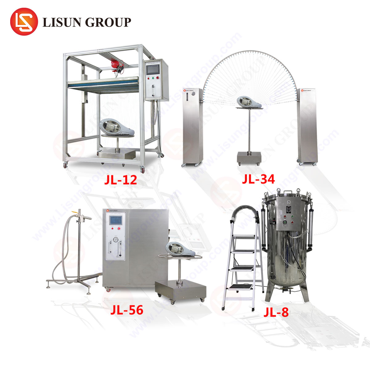
- Lighting Fixtures & Electrical Components: LED arrays, drivers, switches, and sockets are subject to heat from operation and ambient cooling. Thermal shock accelerates the testing of phosphor degradation in LEDs, contact fatigue in relays, and the embrittlement of insulating plastics. It can reveal failures in the thermal interface materials between an LED chip and its heat sink.
- Cable & Wiring Systems: Insulation and jacketing materials are tested for microcracking when flexed at low temperatures after high-temperature exposure, which can compromise dielectric strength and environmental sealing.
Designing a Conformity Assessment Test Protocol
Implementing a thermal shock test is not a matter of arbitrary severity. A scientifically defensible test protocol is derived from a combination of relevant industry standards, known field environmental data, and the product’s failure mode and effects analysis (FMEA). The process typically involves:
- Requirement Definition: Referencing standards like IEC 60068-2-14, JESD22-A106, or automotive-specific standards like ISO 16750-4. These dictate temperature extremes, dwell times, transfer rates, and cycle counts.
- Fixture Design: Creating specimen baskets or racks that hold products in their operational orientation without impeding airflow, yet allowing for rapid thermal energy transfer.
- Profile Development: Programming the chamber (e.g., the HLST-500D) with the specified high/low temperatures, stabilization dwells (often 30 minutes or until the specimen’s slowest-to-respond thermal mass reaches target), and total cycles (commonly 50 to 1,000).
- In-Progress Monitoring: Some protocols may include in-situ monitoring of electrical continuity for daisy-chained assemblies to detect intermittent failures as they occur.
- Post-Test Evaluation: This is critical. It includes visual inspection under magnification, electrical functional testing, and potentially destructive physical analysis (DPA) like cross-sectioning to examine solder joint integrity or scanning acoustic microscopy (SAM) to detect internal delamination.
Comparative Advantages in Chamber Selection and Operation
Selecting an appropriate thermal shock chamber involves evaluating several operational and technical factors. Chambers like the HLST-500D offer distinct advantages in key areas. The cascade compressor refrigeration system provides reliable pull-down to -65°C, a temperature necessary for testing aerospace and high-reliability automotive components. The ≤10-second transfer time, achieved through a robust mechanical drive and optimized basket design, ensures the test meets the stringent “shock” criteria of applicable standards. Furthermore, precise temperature control with fluctuations within ±0.5°C guarantees that the applied stress is consistent and repeatable across tests and laboratories—a necessity for comparative analysis and qualification.
From an operational standpoint, user safety features (like independent overtemperature protection), energy-efficient design in standby modes, and comprehensive data logging capabilities for audit trails contribute to lower total cost of ownership and compliance ease. The chamber’s construction, using materials resistant to thermal fatigue, directly impacts its own longevity and maintenance intervals, reducing downtime over years of rigorous testing.
Data Interpretation and Correlation to Field Reliability
The ultimate value of thermal shock testing lies in the correct interpretation of results and their correlation to expected product lifetime. A “pass” indicates that, within the bounds of the test’s acceleration factors, no latent defects of the types provoked by thermal stress were present. A “fail” provides invaluable forensic data.
The nature of the failure—its location, mechanism, and the cycle count at which it occurred—feeds directly into design and process improvements. For instance, if solder joints on a specific BGA component consistently fail after 200 cycles, the solution may involve modifying the PCB pad design, changing the solder alloy composition, or adjusting the reflow profile. The acceleration factor (AF) linking test cycles to field life can be modeled using relationships like the Coffin-Manson equation for thermo-mechanical fatigue, where the number of cycles to failure is inversely proportional to the temperature swing raised to an exponent. This allows engineers to make quantitative predictions about field reliability based on accelerated test data, transforming a qualitative stress test into a predictive engineering tool.
Conclusion
Thermal shock testing remains an indispensable pillar of product validation strategy. By forcibly subjecting products to the extreme thermodynamic stresses they may encounter—or may accelerate latent flaws—it provides a uncompromising assessment of material compatibility, manufacturing process control, and fundamental design robustness. Equipment such as the HLST-500D Thermal Shock Test Chamber enables the execution of these tests with the precision, repeatability, and standardization required in today’s global, quality-driven industries. The data derived feeds a continuous improvement loop, driving innovations in material science, interconnection technology, and mechanical design, ultimately culminating in products that deliver unwavering performance in the face of environmental extremes.
Frequently Asked Questions (FAQ)
Q1: What is the critical difference between thermal shock testing and thermal cycling?
Thermal shock testing emphasizes an extremely rapid rate of temperature change, typically achieved by physically moving the specimen between two extreme pre-conditioned zones in seconds. The focus is on inducing maximum thermal stress. Thermal cycling usually involves a single chamber where the temperature is ramped up and down at a specified, often slower, rate (e.g., 5°C/min). It is more representative of slower, diurnal cycles and is better for assessing fatigue life over many cycles.
Q2: How do I determine the appropriate high and low temperature setpoints for my product test?
Setpoints are primarily derived from three sources: the governing product standard (e.g., an automotive module may follow ISO 16750-4 which specifies -40°C to +125°C), the product’s specified operational or storage limits as defined in its datasheet, and field environmental data. The test extremes often slightly exceed these limits to incorporate a safety margin, a practice known as “derating” or “applying a stress factor.”
Q3: Why is transfer time so critical in a thermal shock test, and how is it measured?
A prolonged transfer time allows the specimen to begin equilibrating to an intermediate temperature during the move, thereby reducing the actual ΔT experienced and diminishing the “shock” effect. A fast transfer (<10 sec) ensures the specimen's surface and interior are exposed to the full temperature extreme almost instantaneously. It is measured as the time from when the basket begins leaving the first zone until it is fully sealed within the second zone.
Q4: For a chamber like the HLST-500D, what is the importance of “recovery time” and what affects it?
Recovery time is the period required for the chamber (high or low zone) to return to its target setpoint after the thermal mass of the basket and specimens has been introduced. A short recovery time maintains test severity and reduces overall cycle time. It is affected by the chamber’s heating/cooling power, the insulation efficiency, the thermal mass of the load, and the setpoint delta. Overloading a chamber will significantly extend recovery times and alter the test profile.
Q5: Can thermal shock testing be performed on powered, functioning units?
While standard thermal shock is typically performed on unpowered specimens, in-situ monitoring is possible. This often involves running continuous electrical continuity tests (known as event detection) on daisy-chained specimens or using feed-through ports to power and monitor functional units. However, this adds complexity, as cabling must withstand the extreme temperatures and rapid flexing without affecting the transfer mechanism or specimen stress state.